Frames of reference
Before moving into a description of the configuration file syntax, one must understand some basic information about the frames of reference used:
to describe locations of objects on the aircraft,
to specify conditions related to aircraft position and orientation in space,
to assign inputs for a given flight condition.
Reference sources: * JSBSim Reference Manual - Frames of reference * Wikipedia about axes conventions
Structural, or “Construction” Frame
This frame is the manufacturer-style reference used to define points on the aircraft: center of gravity, landing gear contact points, pilot eye-point, point masses, thrusters, and more. In JSBSim aircraft configuration files, many locations are specified in this frame.
In the structural frame, the X-axis runs along fuselage length and points toward the tail, the Y-axis points toward the right wing, and Z is positive upward. A common origin \(O_\mathrm{C}\) is near the front of the aircraft. This frame is often denoted as \(\mathcal{F}_\mathrm{C} = \{O_\mathrm{C}, x_\mathrm{C}, y_\mathrm{C}, z_\mathrm{C}\}\).

Aircraft structural (or construction) frame of reference with origin \(O_\mathrm{C}\). Besides the structural frame axes \(x_\mathrm{C}\), \(y_\mathrm{C}\), and \(z_\mathrm{C}\), the standard body frame axes \(x_\mathrm{B}\), \(y_\mathrm{B}\), and \(z_\mathrm{B}\) are also shown with their origin at the center of mass \(G\). The pilot’s eye-point is located at \(P_\mathrm{EP}\).
The \(x_\mathrm{C}\) axis is often aligned with the fuselage centerline and frequently with thrust axis. Positions along the axes are commonly called stations (\(x_\mathrm{C}\)), buttlines (\(y_\mathrm{C}\)), and waterlines (\(z_\mathrm{C}\)).
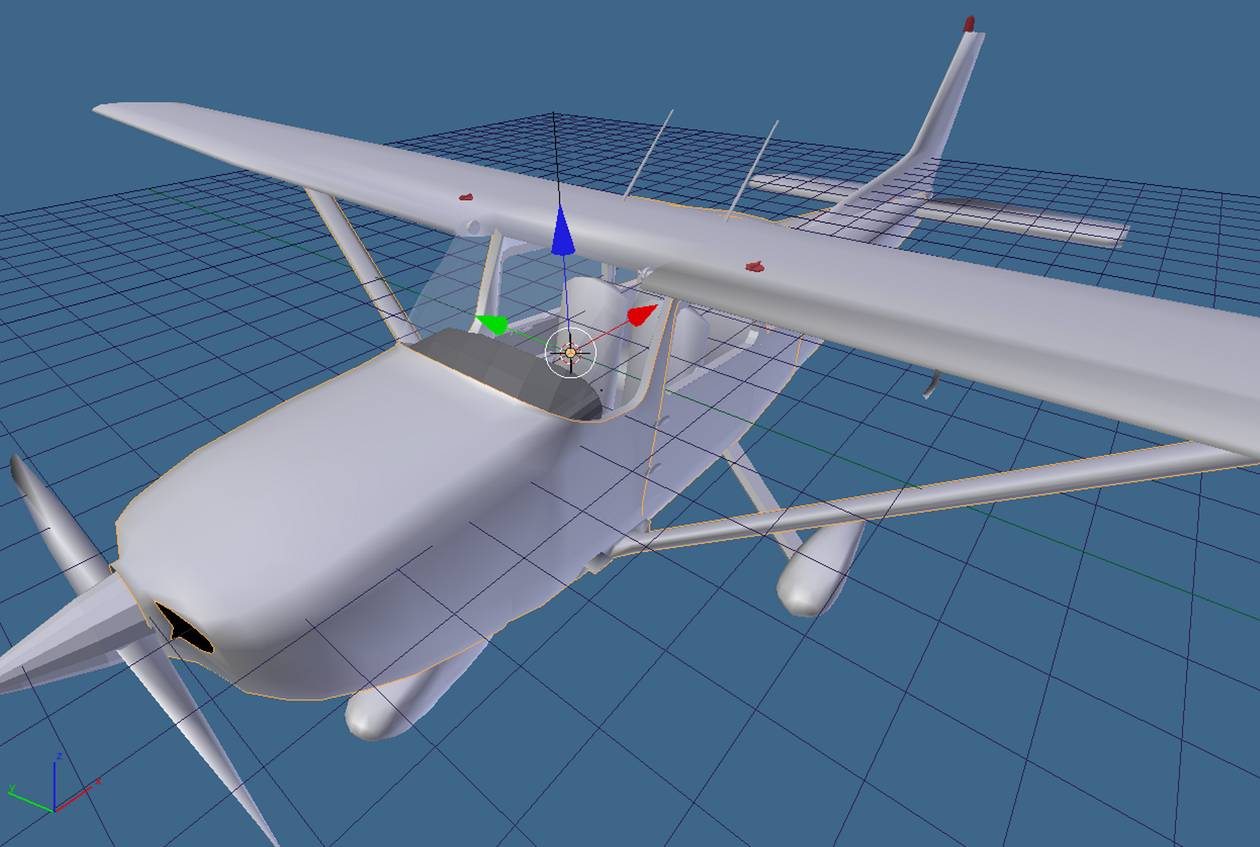
A screenshot taken from the 3D modeling software Blender. The scene shows a model of Cessna 172 with its structural frame \(\mathcal{F}_\mathrm{C} = \{O_\mathrm{C}, x_\mathrm{C}, y_\mathrm{C}, z_\mathrm{C}\}\). The origin \(O_\mathrm{C}\) in this case is located inside the cockpit, near the dashboard.
JSBSim mainly uses relative distances between points, so the absolute origin location is not critical if geometry is consistent.

Center of gravity (CG) position, point \(G\), determined in a construction frame.

Definition of ground contact points in terms of construction frame locations.

Two key point locations \(P_\mathrm{ARP}\) and \(P_\mathrm{CG,EW}\) in the structural frame, respectively, he pole of aerodynamic moments and the Empty Weight CG of the airframe. The shape of the wing root profile and its chord are also sketched.

Besides point \(P_\mathrm{CG,EW}\), are represented two more significant locations, \(P_\mathrm{Pilot}\) and \(P_\mathrm{Right\,Pass}\), where two additional masses are concentrated, respectively, of the pilot and of the right passenger.
Body Frame
In JSBSim, the body frame is equivalent to a 180-degree rotation of the construction frame around \(y_\mathrm{C}\), with origin at the center of mass \(G\). The body frame is often written as \(\mathcal{F}_\mathrm{B} = \{G, x_\mathrm{B}, y_\mathrm{B}, z_\mathrm{B}\}\).
\(x_\mathrm{B}\) points forward (roll axis),
\(y_\mathrm{B}\) points to the right wing (pitch axis),
\(z_\mathrm{B}\) points downward (yaw axis direction convention in body coordinates).

Standard aircraft body axis frame, with origin at the center of gravity \(G\).
Forces and moments are summed in body axes and integrated to obtain translational and rotational states.
Stability, or “Aerodynamic” Frame
This frame is defined by the relative wind orientation with respect to the aircraft. Denote it as \(\mathcal{F}_\mathrm{A} = \{ G, x_\mathrm{A}, y_\mathrm{A}, z_\mathrm{A} \}\).
\(x_\mathrm{A}\) points into the relative wind projected onto the symmetry plane,
\(y_\mathrm{A}\) coincides with \(y_\mathrm{B}\),
\(z_\mathrm{A}\) completes the right-handed triad.
The aerodynamic angles are angle of attack \(\alpha_\mathrm{B}\) and sideslip \(\beta\).

Aerodynamic frame, defining the aerodynamic angles \(\alpha_\mathrm{B}\) and \(\beta\).
In JSBSim usage, the term stability frame commonly refers to this aerodynamic frame. Lift is aligned with \(-z_\mathrm{A}\) and drag with the opposite wind direction.

Banked lift in a steady coordinated turn at constant altitude. The bank angle \(\phi_\mathrm{W}\) is a rotation around the relative wind velocity vector. The motion is freezed in time when the velocity vector is aligned with the North. Coordinated turn means that \(\beta=0\) and constant altitude means that \(x_\mathrm{A}\) is kept horizontal.
Earth-Centered Frames (ECI and ECEF)
The Earth-Centered Inertial frame is \(\mathcal{F}_\mathrm{ECI} = \{ O_\mathrm{ECI}, x_\mathrm{ECI}, y_\mathrm{ECI}, z_\mathrm{ECI} \}\). Its axes are fixed relative to inertial space.
The Earth-Centered Earth-Fixed frame is \(\mathcal{F}_\mathrm{ECEF} = \{ O_\mathrm{ECEF}, x_\mathrm{ECEF}, y_\mathrm{ECEF}, z_\mathrm{ECEF} \}\). Its axes rotate with Earth, with angular rate \(\omega_\mathrm{E}\).

Earth-Centered Inertial (ECI) frame and Earth-Centered Earth-Fixed (ECEF) frame.
North-Oriented Tangent Frame
A local tangent frame can be defined at a point \(O_\mathrm{E}\) on Earth’s surface: \(\mathcal{F}_\mathrm{E} = \{ O_\mathrm{E}, x_\mathrm{E}, y_\mathrm{E}, z_\mathrm{E} \}\). Here \(x_\mathrm{E}\) points North, \(y_\mathrm{E}\) points East, and \(z_\mathrm{E}\) points Down (NED convention).

Earth-Centered Earth-Fixed (ECEF) frame, geografic coordinates, Tangent (T) frame, and local Vertical (V) frame.
Local-Vertical Local-Level Frame (Local NED)
The local vertical frame is \(\mathcal{F}_\mathrm{V} = \{ G, x_\mathrm{V}, y_\mathrm{V}, z_\mathrm{V} \}\). It depends on aircraft position over Earth, not on body attitude.
In this frame, weight has components \((0, 0, mg)\). The aircraft Euler angles \(\psi\), \(\theta\), \(\phi\) (3-2-1 sequence) define body orientation with respect to local NED.

Aircraft body frame and local vertical frame (NED frame). The aircraft Euler angles are also shown: the heading angle \(\psi\) (negative in the picture), the elevation angle \(\theta\), and the roll angle \(\phi\).

Euler angle sequence for an aircraft. The frame \(\mathcal{F}_\mathrm{E} = \{ O_\mathrm{E}, x_\mathrm{E}, y_\mathrm{E}, z_\mathrm{E}\}\) is an Earth-fixed NED coordinate system, with origin the \(O_\mathrm{E}\) somewhere on the ground (or at see level) and the plane \(x_\mathrm{E} y_\mathrm{E}\) tangent to the Earth surface. If the ground track point \(G_\mathrm{GT}\) is not too far from \(O_\mathrm{E}\), the Earth frame \(\mathcal{F}_\mathrm{E}\) axes are parallel to those of the local NED frame \(\mathcal{F}_\mathrm{V} = \{ G, x_\mathrm{V}, y_\mathrm{V}, z_\mathrm{V}\}\).
Wind Frame
The wind frame \(\mathcal{F}_\mathrm{W} = \{ G, x_\mathrm{W}, y_\mathrm{W}, z_\mathrm{W} \}\) uses:
\(x_\mathrm{W}\) along velocity direction,
\(z_\mathrm{W}\) along lift line (equal to \(z_\mathrm{A}\)),
\(y_\mathrm{W}\) completing the right-handed frame.
Drag and lift in wind axes satisfy \(X_\mathrm{W} = -D\) and \(Z_\mathrm{W} = -L\). When \(\beta = 0\), wind and aerodynamic frames coincide.

Standard frames of reference and aircraft in climbing flight in calm air. The CG velocity vector \(\boldsymbol{V}\) forms the flight path angle \(\gamma\) with the horizontal plane. The standard three aerodynamic resultant force components \(D\), \(L\) and \(Y_\mathrm{A}\) are also shown.
The relation among wind, aerodynamic, and body frames is:
Using drag, side force and lift, body-axis components are written as: