Anatomy of Airplane Flight
In this section we recall some essential definitions that are useful for the study of airplane flight mechanics.
Aerodynamic Angles
The first figure introduces the two aerodynamic angles that generate the aerodynamic forces and moments acting on the airplane. These angles are the aircraft sideslip angle $\beta$ and the aircraft (absolute) angle of attack $\alpha$. The sideslip $\beta$ is the angle formed by the instantaneous CoG velocity vector $\boldsymbol{V}$ and its projection onto the airplane’s symmetry plane. The projection is the aerodynamic axis called $x_\mathrm{A}$, a baricentric axis, and shown in the figure.
If the pilot sees a relative wing velocity $\boldsymbol{V} _ {\infty} = -\boldsymbol{V}$ coming from the right then the sideslip $\beta$ is positive by definition. If the relative wind is in the plane of symmetry, i.e. $\beta = 0$, the aircraft is in aerodynamically symmetric flight and the direction of $\boldsymbol{V}$ coincides with the direction of $x_\mathrm{A}$.
The angle between axes $x_\mathrm{A}$ and $x_\mathrm{B}$ is the aircraft body-angle of attack $\alpha_\mathrm{B}$. The angle $\alpha = \alpha_\mathrm{B} + \mu_x$ between $x_\mathrm{A}$ and the zero-lift line of the wing is the aircraft absolute angle of attack $\alpha$. This angle is shown in the above figure.
The aerodynamic axis $z_\mathrm{A}$ is taken, by construction, in the aircraft symmetry plane and positively oriented as shown. The remaining aerodynamic axis $y_\mathrm{A}$ completes the frame and coincides with the body axis $y_\mathrm{B}$.
Definitions of the Aircraft Lift and Drag
Next figure represents the simple case of an airplane in symmetric, wings level flight, with the CoG moving along a straight and horizontal trajectory. By definition, the lift $L$ is such that $-L$ is the component of the resultant aerodynamic force \(\boldsymbol{F}_\mathrm{A}\) on the axis $z_\mathrm{A}$. The drag $D$ is so defined that $-D$ is the component of \(\boldsymbol{F}_\mathrm{A}\) along the axis $x_\mathrm{A}$. In symmetric flight these are the only two components of $\boldsymbol{F}_\mathrm{A}$ and they are shown in the figure.
The flight condition considered below is such that the plane $x_\mathrm{A} y_\mathrm{A}$ is horizontal, that is, normal to the local vertical direction given by the weight vector $\boldsymbol{W} = m \boldsymbol{g}$ passing through the CoG (point $G$). The attitude of the fuselage is such that the body axis $x_\mathrm{B}$ forms an angle $\alpha_\mathrm{B}$ with respect to the relative wind, being in this particular case the horizontal vector $-\boldsymbol{V}$.
This angle is also the angle formed by the fuselage longitudinal axis $x_\mathrm{B}$ with the horizontal plane, which is called elevation angle (sometimes erroneously also called ‘pitch angle’). The simple flight condition considered here features a horizontal CoG trajectory but an inclined fuselage. This means that the angle $\theta$ coincides with the aerodynamic angle $\alpha_\mathrm{B}$.
In addition to the aerodynamic forces and aircraft weight, in the above figure is also shown the thrust $T$. This is the intensity of the thrust vector, which is a force applied somewhere near the propulsion system and properly oriented with respect to the airplane’s body axes. Due to the low values of $\alpha_\mathrm{B}$ in normal flight conditions, in many cases it is an acceptable approximation to assume a thrust vector aligned with the flight speed as depicted above.
Climb Angle and Aircraft Elevation Angle (Fuselage Attitude)
A slightly different flight condition is represented below. The CoG motion occurs along a curved trajectory and the picture shows a moment in time when the velocity vector $\boldsymbol{V}$ is not horizontal but has an inclination $\gamma$ over the horizontal. This angle is called flight path angle or climb angle and is positive as shown, i.e. when the aircraft is climbing.
The above picture clearly shows the difference that might occur in wings level flight between the elevation angle $\theta$ and the climb angle $\gamma$
\[\alpha_\mathrm{B} = \theta - \gamma \label{eq:Flight:alpha:gamma:theta}\]In a climbing flight the airplane fuselage has an attitude $\theta$ over the horizon that differs from the attitude $\gamma$ of the CoG velocity vector $\boldsymbol{V}$.
Next two figures represent an accelerated flight starting from a wings level, constant altitude motion, and developing into a climb. The motion is referred to a frame of reference \(\left\{ O_\mathrm{E}, x_\mathrm{E}, y_\mathrm{E}, z_\mathrm{E}\right\}\) fixed with the Earth named Earth frame. The origin $O_\mathrm{E}$ is placed somewhere on the ground (at seal level). The orientation of Earth axes follows the North-East-Down convention: $x_\mathrm{E}$ points towards the North, $y_\mathrm{E}$ is positively oriented towards the East, and $z_\mathrm{E}$ completes the frame pointing down towards the center of the Earth.
The above figure is a side view of the climbing flight showing again the difference between the aircraft attitude angle $theta$ and the flight path angle $\gamma$.
Thrust Orientation in Body-Axes
The thrust vector of a single-engine propeller aircraft is shown below. In conventional aircraft configurations (with non-orientable thrusters) the thrust vector has a fixed orientation with respect to the fuselage, which is represented by the angle $\mu_T$.
In general, the resultant thrust vector is applied to a point $C_T$, fixed with the aircraft, along a direction called thrust action line. This line might have a nonzero distance $h_T$ from the CoG; hence the thrust can provide a nonzero pitching moment about the point $G$.
Wings Level Symmetric Flight
The figure below summarizes the concepts discussed so far. An aircraft flying with wings level in symmetric conditions, i.e. with zero sideslip, always keeps his symmetry plane vertical. Hence the four fundamental forces involved in symmetric flight, i.e. lift, drag, thrust and the weight vector, are always in the same vertical plane. In this circumstance a non accelerated flight ($V = \mathrm{const}$) along a rectilinear CoG trajectory occurs at an angle of climb $\gamma$ with the fuselage at an attitude angle $\theta = \gamma + \alpha_\mathrm{B}$. In particular, such a flight might occurr along an horizontal trajectory, in which case $\gamma = 0$ and $\theta = \alpha_\mathrm{B}$.
When the thrust line is non-baricentric, the equilibrium in pitch during flight is reached when the moment $\mathcal{M}_T$ around the CoG provided by the thrust vector is equal and opposite to the resultant baricentric aerodynamic moment $\mathcal{M} _ \mathrm{A}$.
The next scheme of forces is the result of the common two assumptions in the study of aircraft performance:
- The angles involved are small, i.e. $\alpha_\mathrm{B}$, $\mu_T$, $\gamma$, and $\theta$. Whitin this assumption, in studies related to climb or descending flight the angle $\gamma$ is important therefore is retained in thos formulations, in which cases the equality $\gamma = \theta$ holds.
- The thrust line is baricentric. For the assumption of small $\alpha_\mathrm{B}$, results in a thrust aligned with the CoG velocity $\boldsymbol{V}$.
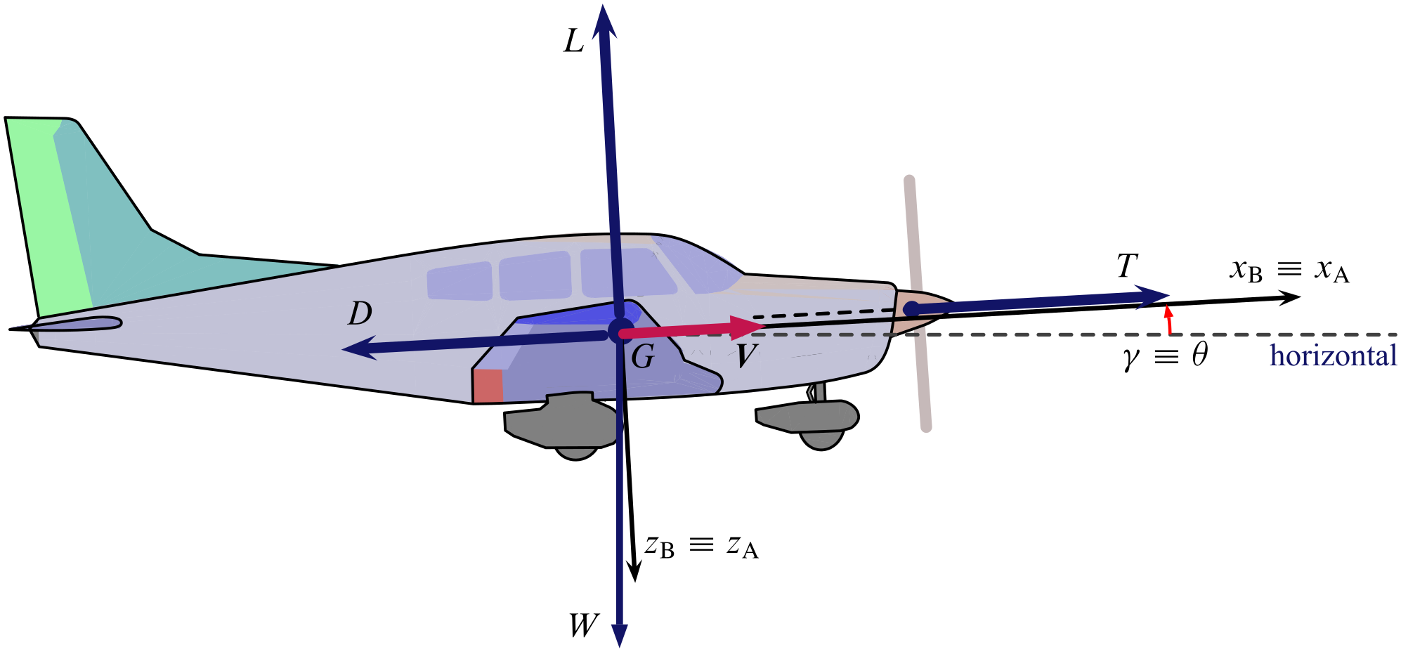
The above scheme of forces becomes even simpler for a wings level, symmetric flight along a horizontal trajectory, i.e. $\gamma = 0$. In this case thrust and drag forces are opposed and horizontal; weight and lift forces are aligned, opposed and vertical.