Airspeeds
Airspeed Measures
The airspeed is usually determined in flight by pressure measurements at the current altitude. The knowlegde of pressure permits the calculation of the airspeed provided that the instrument in use is properly calibrated.
There is an aerodynamic instrument that actually measures the total pressure at a point in the airflow: the Pitot tube. The Pitot tube is utilized to measure the total combined pressures that are present when an aircraft moves through the air. Static pressure, also known as ambient pressure, is always present whether an aircraft is moving or at rest. It is simply the barometric pressure in the local area. Dynamic pressure, also called ‘Q-bar’ in aviation jargon,
\[\bar{q} = \frac{1}{2} \rho V^2\]is present only when an aircraft is in motion; therefore, it can be thought of as a pressure due to motion. The above definition of dynamic pressure remains the same for flows of all types, incompressible to hypersonic.
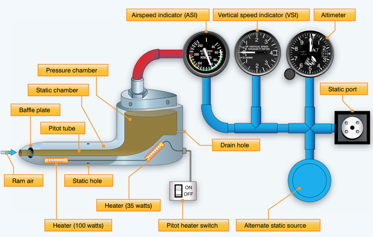
A scheme of a Pitot-satic system mounted on an aircraft is shown in the figure below.
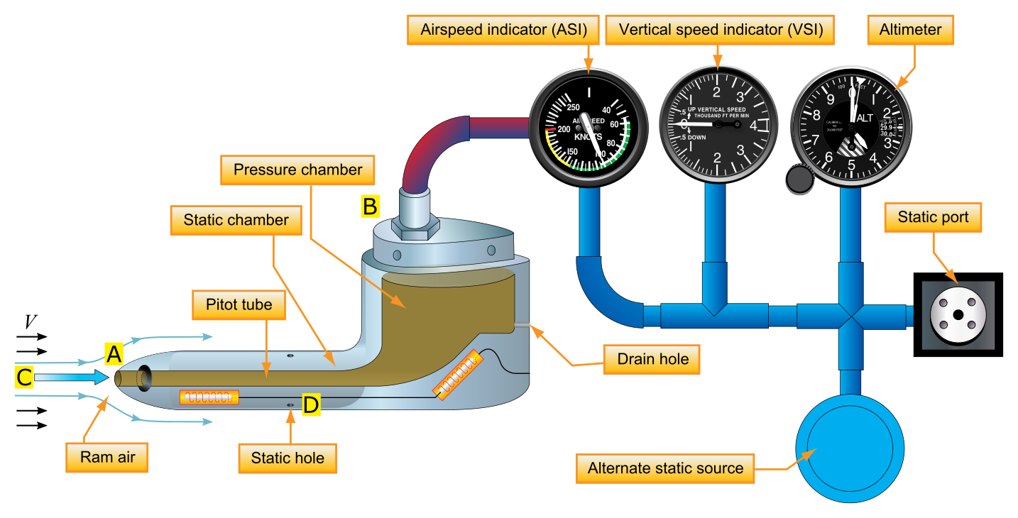
Pitot probes
A Pitot tube consists of a tube placed parallel to the flow and open to the flow at one end (point A). The other end of the tube (point B) is closed. Now imagine that the flow is first started. Gas will pile up inside the tube. After a few moments, there will be no motion inside the tube because the gas has nowhere to go – the gas will stagnate once steady-state conditions have been reached. In fact, the gas will be stagnant everywhere inside the tube, including at point A. As a result, the flow field sees the open end of the Pitot tube (point A) as an obstruction, and a fluid element moving along the streamline, labeled C, has no choice but to stop when it arrives at point A. Because no heat has been exchanged, and friction is negligible, this process will be isentropic; that is, a fluid element moving along streamlines from C to A will be isentropically brought to rest at point A by the very presence of the Pitot tube. Therefore, the pressure at point A is, truly speaking, the total pressure $p_0$. This pressure will be transmitted throughout the Pitot tube; and if a pressure gauge is placed at point B, it will in actuality measure the total pressure of the flow. In this fashion, a Pitot tube is an instrument that measures the total pressure of a flow. By definition, any point of a flow where the speed is zero is called a stagnation point. In the previous figure, point A is a stagnation point.
Probes based on the Pitot principle that are capable of measuring the stagnation pressure are called simply Pitot probes.
Pitot-static probes
Consider the static hole D in the above figure. It is a small hole in the external surface of the Pitot tube, called a static pressure orifice. Because the surface is parallel to the flow, only the random motion of the gas molecules will be felt by the surface itself. In other words, the surface pressure is indeed the static pressure $p$. This will be the pressure at the orifice at point D. In contrast, the Pitot tube at point A will feel the total pressure $p_0$. Normally the static pressure orifice at point D and the Pitot tube at point B are connected across a pressure gauge, that will measure the difference between total and static pressure $p_0 - p$.
The pressure difference $p_0 - p$ gives a measure of the flow velocity $V$. A combination of a total pressure measurement and a static pressure measurement allows to measure the velocity at a given point in a flow. These two measurements can be combined in the same instrument, a Pitot-static probe, as illustrated in the last figure. A Pitot-static probe measures $p_0$ at the nose of the probe and $p$ at a point on the probe surface downstream of the nose. The pressure difference $p_0 - p$ yields the velocity $V$, but the quantitative formulation differs depending on whether the flow is low speed (incompressible), high-speed subsonic, or supersonic.
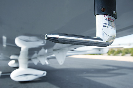
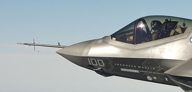
Either Pitot tubes or Pitot-static tubes are used to measure the airspeed of airplanes. Such tubes can be seen extending from airplane wing tips, with the tube oriented in the flight direction, or from the nose of fuselages.
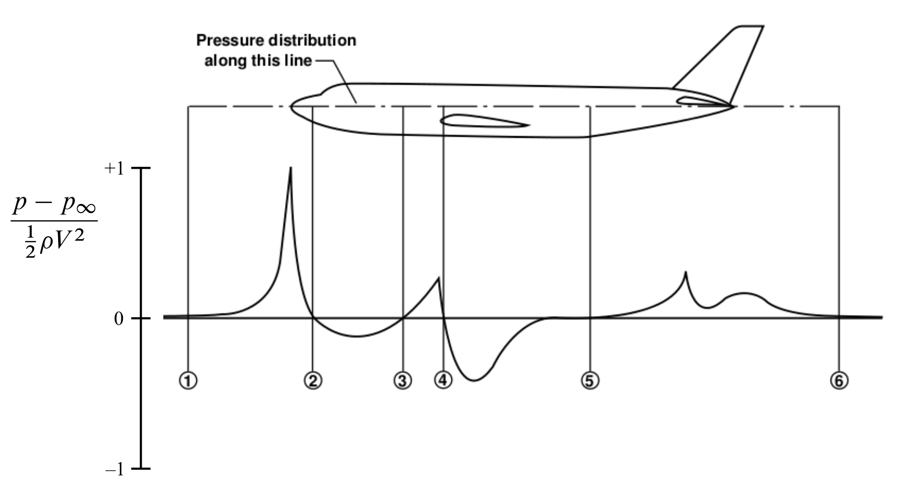
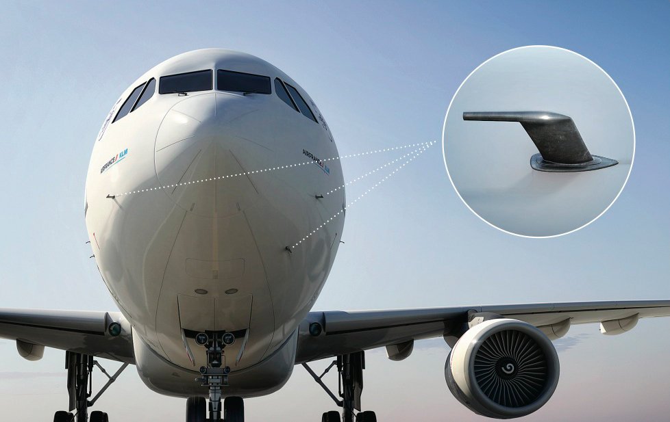
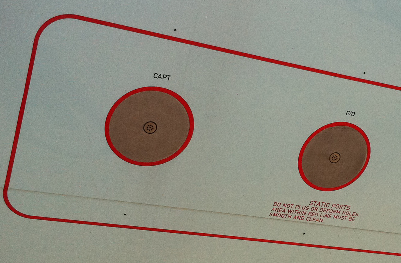
If a Pitot tube by itself is used instead of a Pitot-static tube, then the ambient static pressure in the atmosphere around the airplane is obtained from a static pressure orifice placed strategically on the airplane surface. See for example the above figure. It is placed where the surface pressure is nearly the same as the pressure of the surrounding atmosphere. Such a location is found by experience. It is generally on the fuselage somewhere between the nose and the wing. An example of static probes located on the fuselage is shown by next photo.
Incompressible Subsonic Formulation
At point D, i.e. at one of the static holes of the Pitot tube, the pressure is $p$ and the velocity is $V$ (supervelocities due to the shape of the external shape of the tube are neglectable). At point A, the pressure is $p_0$ and the velocity is zero. Applying Bernoulli’s equation at points A and D, we obtain
\[p_0 = p + \frac{1}{2}\rho \, V^2 \label{eq:Airpeeds:Bernoulli}\]that is, the difference in static pressure between the points A and D is the dynamic pressure at point D. The last relation holds for incompressible flows only. The total pressure equals the sum of the static and the dynamic pressure. This yields the desired relation between $V$ and the difference $p_0 - p$:
\[\color{red}{ V = \sqrt{ \mathstrut 2\, \frac{p_0 - p}{\rho}} } \label{eq:Airpeeds:V:Incompressible}\]In the incompressible regime where the density $\rho$ is a known constant value, the above formula allows the calculation of flow velocity from a measurement of $p_0 - p$, obtained from a Pitot-static tube. The constant density $\rho$ value can be obtained by measuring $p$ and $T$ and applying the equation of state to calculate $\rho = p/(R\,T)$.
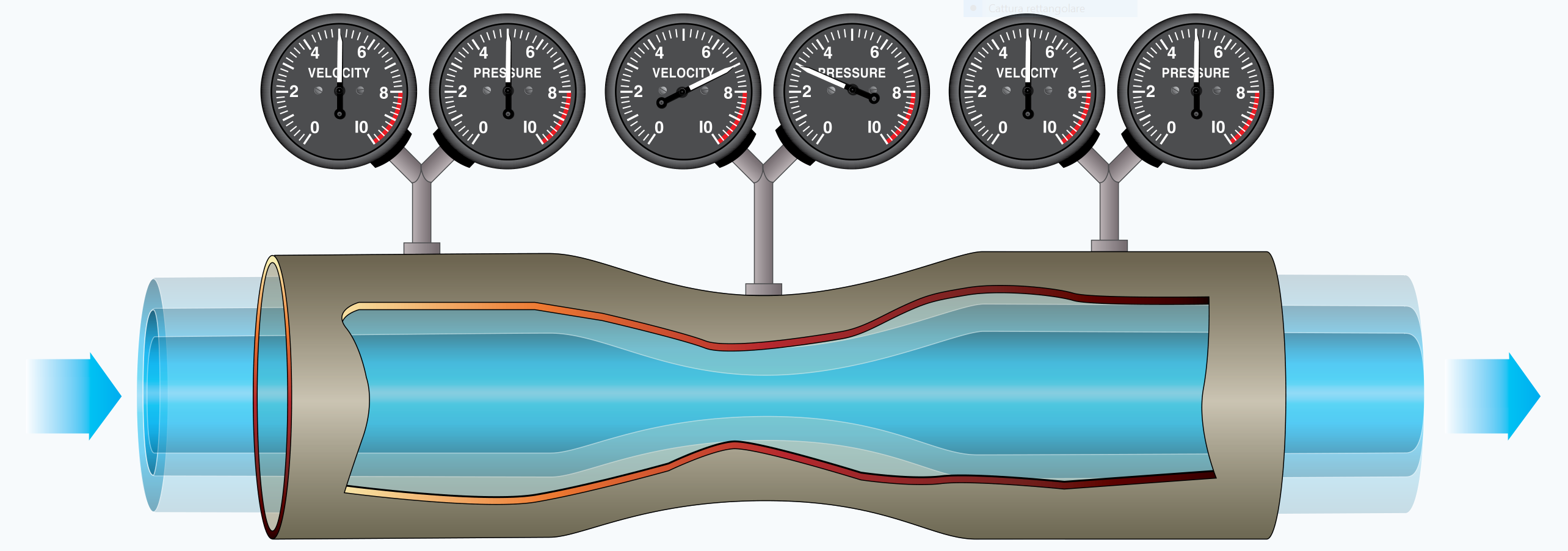
The implications of equation (\ref{eq:Airpeeds:Bernoulli}) for uncompressible flows are often visualized by the Venturi-tube experiment shown below. Being the sum of static and dynamic pressure a constant, this the instruments show a pressure decrease where the local airstream accelerates, and a pressure rise where the airspeeds decreases.
In those points in the flow where the local velocity becomes zero (not occurring in the above experiment), the local static pressure reaches the value of the airflow total pressure $p_0$. The condition $V = 0$ defines a stagnation point in the flow.
The values of $p_0$ obtained from the Pitot probe and $p$ obtained from the static pressure orifice enable calculation of the airplane’s speed through the air using equation (\ref{eq:Airpeeds:V:Incompressible}), as long as the airplane’s velocity is low enough to justify the assumption of incompressible flow (that is, for veloci- ties less than 300 ft/s). In actual practice, the measurements of $p_0$ and $p$ are joined across a differential pressure gauge that is calibrated in terms of airspeed, using relation (\ref{eq:Airpeeds:V:Incompressible}). This airspeed indicator is a dial in the cockpit, with units of velocity, say miles per hour, on the dial.
However, in determining the calibration (that is, in determining what values of miles per hour go along with given values of $p_0 - p$), the engineer must decide what value of $\rho$ to use in such equation. If $\rho$ is the true value, somehow measured in the actual air around the airplane, then equation (\ref{eq:Airpeeds:V:Incompressible}) gives the true airspeed (TAS) of the airplane in the incompressible regime:
\[\color{red}{ V_\mathrm{TAS} } = \sqrt{ \mathstrut 2\, \frac{p_0 - p}{\rho}} \label{eq:Airpeeds:V:Incompressible:TAS}\]However, measurement of atmospheric air density directly at the airplane’s location is difficult. Therefore, for practical reasons, the airspeed indicators on low-speed airplanes are calibrated by using the standard sea-level value of $\rho_\mathrm{SL}$, in equation (\ref{eq:Airpeeds:V:Incompressible:TAS}). This gives a value of velocity called the equivalent airspeed (EAS):
\[\color{red}{ V_\mathrm{EAS} } = \sqrt{ \mathstrut 2\, \frac{p_0 - p}{\rho_\mathrm{SL}}} \label{eq:Airpeeds:V:Incompressible:EAS}\]The equivalent airspeed $V_\mathrm{EAS}$ differs slightly from $V_\mathrm{TAS}$, the difference being the factor $\sqrt{\mathstrut\sigma}=(\rho/\rho_\mathrm{SL})^\frac{1}{2}$. At altitudes near sea level, this difference is small.
Compressible Subsonic Formulation
The results discussed in previous section are valid for airflows where the flight Mach number $M < 0.3$, that is, where the flow can reasonably be assumed to be incompressible. This is the flight regime of small, piston-engine private aircraft. For higher-speed flows, but where the Mach number is still less than 1 (high-speed subsonic flows), other equations must be used. This is the flight regime of commercial jet transports such as the modern airliners and of many military aircraft. For these cases, compressibility must be taken into account, as follows.
Assume that the air can be modelled as a perfect gas, whose equation of state is:
\[p = \rho \, R \, T \label{eq:Airpeeds:rhoRT}\]or, similarly
\[c_p \, T = \frac{a^2}{\gamma - 1} = \frac{\gamma}{\gamma - 1} \frac{p}{\rho} \label{eq:Airpeeds:cpT}\]with $c_p$ the air isobaric specific heat, and $\gamma = 1.4$ the specific heat ratio.
Consider a Pitot tube in a flow with velocity $V$, with $V$ high enough that compressibility must be taken into account. Assume that the flow is isentropically compressed to zero velocity at the stagnation point on the nose of the probe. The values of the stagnation, or total, pressure and temperature at this point are $p_0$ and $T_0$, respectively. The following energy equation holds:
\[c_p \, T + \frac{1}{2} V^2 = c_p \, T_0 \label{eq:Airpeeds:Energy:A}\]expressing the conservation of total energy from a point in the free-stream flow (point C) where the temperature and velocity are $T$ and $V$, respectively, and the stagnation point (point A), where the velocity is zero and the temperature is $T_0$,
The equation (\ref{eq:Airpeeds:Energy:A}) is rewritten as
\[T_0 = T \left( 1 + \frac{V^2}{2\,c_p \, T} \right) \label{eq:Airpeeds:Energy:B}\]Substituting (\ref{eq:Airpeeds:cpT}) the above equation becomes
\[T_0 = T \left( 1 + \frac{\gamma - 1}{2}\,\frac{V^2}{a^2} \right) \label{eq:Airpeeds:Energy:C}\]or
\[\color{red}{ \frac{T_0}{T} = 1 + \frac{\gamma - 1}{2}\,M^2 } \label{eq:Airpeeds:Energy:Mach}\]Because the gas is isentropically compressed at the nose of the Pitot probe the following equation
\[\frac{p_0}{p} = \left( \frac{T_0}{T} \right)^{\gamma/(\gamma - 1)} \label{eq:Airpeeds:Isentropic:Flow:p}\]holds between the free stream and the stagnation point. Therefore, from equation (\ref{eq:Airpeeds:Energy:Mach}), we obtain
\[\color{red}{ \frac{p_0}{p} = \left( 1 + \frac{\gamma - 1}{2}\,M^2 \right)^{\gamma/(\gamma - 1)} } \label{eq:Airpeeds:Isentropic:Flow:Energy:p}\]Equations (\ref{eq:Airpeeds:Energy:Mach}) and (\ref{eq:Airpeeds:Isentropic:Flow:Energy:p}) are fundamental and important relations for compressible, isentropic flow. These equations demonstrate the powerful influence of Mach number in aerodynamic flow calculations. It is very important to note that the ratios $T_0/T$, $p_0/p$ as well as $\rho_0/\rho$ are functions of $M$ only (assuming that $\gamma$ is known; $\gamma = 1.4$ for normal air).
Now, solving equation (\ref{eq:Airpeeds:Isentropic:Flow:Energy:p}) for $M$ we obtain
\[\color{red}{ M^2 = \frac{2}{\gamma - 1} \left[ \left(\frac{p_0}{p}\right)^{(\gamma - 1)/\gamma} - 1 \right] } \label{eq:Airpeeds:Isentropic:Flow:Energy:Mach}\]Hence, for subsonic compressible flow, the ratio of total to static pressure $p_0/p$ is a direct measure of Mach number. Thus, individual measurements of $p_0$ and $p$ in conjunction with equation (\ref{eq:Airpeeds:Isentropic:Flow:Energy:Mach}) can be used to calibrate an instrument in the cockpit of an airplane called a Mach meter, where the dial reads directly in terms of the flight Mach number of the airplane.
To obtain the actual flight velocity, recall that $M = V/a$ so Eq. (\ref{eq:Airpeeds:Isentropic:Flow:Energy:Mach}) becomes
\[V^2 = \frac{2\, a^2}{\gamma - 1} \left[ \left(\frac{p_0}{p}\right)^{(\gamma - 1)/\gamma} - 1 \right] \label{eq:Airpeeds:Isentropic:Flow:Energy:V:A}\]The above expression can be rearranged algebraically as follows:
\[V^2 = \frac{2\, a^2}{\gamma - 1} \left[ \left(\frac{\color{red}{p_0 - p}}{p} + 1\right)^{(\gamma - 1)/\gamma} - 1 \right] \label{eq:Airpeeds:Isentropic:Flow:Energy:V:B}\]Equation (\ref{eq:Airpeeds:Isentropic:Flow:Energy:V:B}) gives the true airspeed of the airplane in the subsonic compressible regime:
\[\color{red}{ V_\mathrm{TAS} = \left\{ \frac{2\, a^2}{\gamma - 1} \left[ \left( 1 + \frac{p_0 - p}{p}\right)^{(\gamma - 1)/\gamma} - 1 \right]\right\}^\frac{1}{2} } \label{eq:Airpeeds:TAS:Subsonic:Compressible}\]However, the fundamental formula (\ref{eq:Airpeeds:TAS:Subsonic:Compressible}) requires a knowledge of the sound speed $a(h)$ at the flight altitude and hence the local ambient temperature $T(h)$. The static temperature in the air surrounding the airplane is difficult to measure. Therefore, all high-speed subsonic airspeed indicators are calibrated from a reformulation of equation (\ref{eq:Airpeeds:TAS:Subsonic:Compressible}), assuming that $a(h)$ is equal to the standard sea-level value $a_\mathrm{SL} = 340.3\,\mathrm{m/s} = 1116\,\mathrm{m/s}$. Moreover, the airspeed indicator is designed to sense the actual pressure difference $p_0 - p$ in formula (\ref{eq:Airpeeds:TAS:Subsonic:Compressible}), not the pressure ratio $p_0/p$, as appears in equation (\ref{eq:Airpeeds:Isentropic:Flow:Energy:V:A}). Hence, the form of the above equation becomes the following calibration formula:
\[V_\mathrm{Calibration-Formula} = \left\{ \frac{2\, \color{blue}{a_\mathrm{SL}^2}}{\gamma - 1} \left[ \left( 1 + \frac{\color{red}{p_0 - p}}{\color{blue}{p_\mathrm{SL}}}\right)^{(\gamma - 1)/\gamma} - 1 \right]\right\}^\frac{1}{2} \label{eq:Airpeeds:Calibration:Formula}\]where $a_\mathrm{SL}$, and $p_\mathrm{SL}$, are the standard sea-level values of the speed of sound and static pressure, respectively. As explained below, this expression coincides with the ‘indicated airspeed’, because this is the formula used to calibrate (on ground) the airspeed indicator instrument.
Supersonic Formulation
Airspeed measurements in supersonic flow (that is, for $M > 1$) are qualitatively different from those for subsonic flow. In supersonic flow, a shock wave will form ahead of the Pitot tube as shown in the next figure.
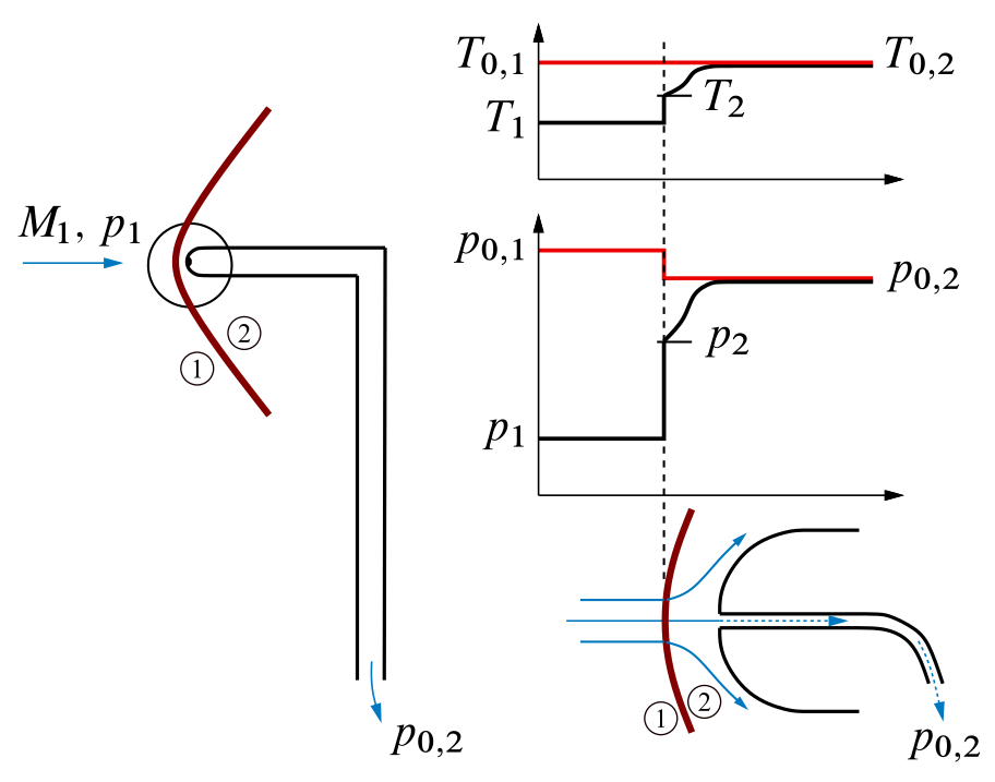
Shock waves are very thin regions of the flow across which some severe changes in the flow properties take place. Specifically, as a fluid element flows through a shockwave, from condition ‘1’ to condition ‘2’,
- The Mach number decreases.
- The static pressure increases.
- The static temperature increases.
- The flow velocity decreases.
- The total pressure $p_0$ decreases.
- The total temperature $T_0$ stays the same for a perfect gas.
These changes across a shock wave are shown in the previous figure. How and why does a shock wave form in supersonic flow? There are various answers with various degrees of sophistication. Within the thin structure of a shock wave itself, very large friction and thermal conduction effects are taking place. Hence, neither adiabatic nor frictionless conditions hold; therefore, the flow is not isentropic. A major consequence is that the total pressure $p_0$ is smaller behind the shock wave than in front of it. In turn, the total pressure measured at the nose of the Pitot probe in supersonic flow will not be the same value as that associated with the free stream – that is, as associated with $M_1$. Consequently, a separate shock wave theory must be applied to relate the Pitot tube measurement to the value of $M_1$. This theory is beyond the scope of this material, but the resulting formula is given here for the sake of completeness:
\[\color{red}{ \frac{p_{0,2}}{p_1} = \left[ \frac{(\gamma + 1)^2 \,M_1^2}{4\,\gamma\,M_1^2 - 2(\gamma -1)} \right]^{\gamma/(\gamma - 1)} \, \frac{1 - \gamma + 2\gamma\,M_1^2}{\gamma + 1} } \label{eq:Airpeeds:Supersonic:Rayleigh}\]This equation is called the Rayleigh Pitot tube formula. It relates the Pitot tube measurement of total pressure behind the shock wave, $p_{0,2}$, and a measurement of free-stream static pressure $p_\infty = p_1$ (again obtained by a static pressure orifice somewhere on the surface of the airplane) to the free-stream supersonic Mach number $M_1$. In this fashion, measurements of $p_{0,2}$ and $p_1$, along with equation (\ref{eq:Airpeeds:Supersonic:Rayleigh}), allow the calibration of a Mach meter for supersonic flight.
Airspeed Definitions
Indicated Airspeed (IAS)
Indicated airspeed (IAS) is the airspeed $V_\mathrm{IAS}$ read directly from the airspeed indicator (ASI) on an aircraft, driven by the pitot-static system. It uses the difference between total pressure and static pressure, provided by the system, to either mechanically or electronically measure dynamic pressure. The dynamic pressure includes terms for both density and airspeed. Since the airspeed indicator cannot know the density, it is by design calibrated to assume the sea level standard atmospheric density when calculating airspeed. Since the actual density will vary considerably from this assumed value as the aircraft changes altitude, IAS varies considerably from true airspeed (TAS), the relative velocity between the aircraft and the surrounding air mass. Ideally, if the ambient static pressure $p=p_\infty$ was measured with no errors, it would be:
\[V_\mathrm{IAS} = \left\{ \frac{2\, \color{blue}{a_\mathrm{SL}^2}}{\gamma - 1} \left[ \left( 1 + \frac{\color{red}{p_0 - p}}{\color{blue}{p_\mathrm{SL}}}\right)^{(\gamma - 1)/\gamma} - 1 \right]\right\}^\frac{1}{2} \quad (\, = V_\mathrm{CAS} \;\mathrm{neglecting\; position\; errors}\,) \label{eq:Airpeeds:CAS:IAS:No:Errors}\]Calibrated Airspeed (CAS)
In practice, the measured static pressure $p$ differs from the ambient pressure at the flight altitude due to chosen position of static probes. This kind of error can minimized but is unavoidable. Therefore, the calibrated airspeed (CAS) defined above is the IAS corrected for instrument and position error, which are characterized experimentally by flight test engineers before the manufacturer obtains the final certification to fly the aircraft.
For instance, the expression (\ref{eq:Airpeeds:CAS:IAS:No:Errors}) given above for subsonic flight in compressible regime, assuming that $V_\mathrm{CAS}=V_\mathrm{IAS}$, can be reformulated as follows:
\[V_\mathrm{CAS} = V_\mathrm{IAS} + {\color{green}{ \Delta V_{\mathrm{IAS}} }} = \left\{ \frac{2\, \color{blue}{a_\mathrm{SL}^2}}{\gamma - 1} \left[ \left( 1 + \frac{\color{red}{p_0 - p}}{\color{blue}{p_\mathrm{SL}}}\right)^{(\gamma - 1)/\gamma} - 1 \right]\right\}^\frac{1}{2} + \color{green}{\Delta V_\mathrm{IAS}} \label{eq:Airpeeds:CAS:IAS}\]Flight manuals (or flight management computers) report the tabulated values of the correction $\Delta V_\mathrm{IAS}$ to be applied to the $V_\mathrm{IAS}$ as a function of $V_\mathrm{IAS}$ itself and of the aircraft configuration status (e.g. in cruise, at take-off, with speedbreakers deployed). Next figure shows this correction function for the military jet trainer Aermacchi MB-336.

Equivalent Airspeed (EAS)
Equivalent airspeed (EAS) is the speed obtained by the CAS formula (\ref{eq:Airpeeds:CAS:IAS}) by replacing the value of $p_\mathrm{SL}$ with the effective value of the static pressure at the flight altitude.
\[V_\mathrm{EAS} = \left\{ \frac{2\,\gamma}{\gamma - 1} \frac{\color{red}{p}}{\rho_\mathrm{SL}} \left[ \left( 1 + \frac{\color{red}{p_0 - p}}{\color{red}{p}}\right)^{(\gamma - 1)/\gamma} - 1 \right]\right\}^\frac{1}{2} \label{eq:Airpeeds:EAS}\]From the above formulas one can express the ratio
\[\frac{V_\mathrm{EAS}}{V_\mathrm{CAS}} = \sqrt{\mathstrut \frac{\color{red}{p}}{\color{blue}{p_\mathrm{SL}}}} \, \frac{ \left[ \left( 1 + \dfrac{\color{red}{p_0 - p}}{\color{red}{p}}\right)^{(\gamma - 1)/\gamma} - 1 \right]^\frac{1}{2} }{ \left[ \left( 1 + \dfrac{\color{red}{p_0 - p}}{\color{blue}{p_\mathrm{SL}}}\right)^{(\gamma - 1)/\gamma} - 1 \right]^\frac{1}{2} } \label{eq:Airpeeds:CAS:Ratio}\]and observe that it is always $\color{red}{V_\mathrm{EAS} < V_\mathrm{CAS}}$.
Flight manuals (or flight management computers) allow to calculate the $V_\mathrm{EAS}$ from the CAS by providing the correction values $\Delta V_\mathrm{CAS}$ to be used in the correction formula
\[V_\mathrm{EAS} = V_\mathrm{CAS} + \color{green}{ \Delta V_\mathrm{CAS} } \label{eq:Airpeeds:CAS:To:EAS}\]The corrections are practically calculated from the formula (\ref{eq:Airpeeds:CAS:Ratio}) as follows
\[{\color{green}{ \Delta V_\mathrm{CAS} }}= V_\mathrm{EAS} - V_\mathrm{CAS} = V_\mathrm{CAS} \, \left( {\color{red}{ \frac{V_\mathrm{EAS}}{V_\mathrm{CAS}} }} - 1\right) \label{eq:Airpeeds:Delta:CAS}\]It has to be observed that the concept of equivalent airspeed has a broader meaning than just a value that comes from an airspeed indicator, which uses the standard sea-level density to determine its readout, as first explained above.
It is important to reinforce that dynamic pressure is a definition, defined by the quantity $\bar{q} = \frac{1}{2}\rho V^2$. Now imagine the aircraft is flying at standard sea level, where the free-stream density is $\rho_\mathrm{SL} = 1.225\,\mathrm{kg/m}^3$.
Question: What velocity $V_\mathrm{SL}$ would it have to have at standard sea level to experience the same dynamic pressure that it had when flying at $V$ at the altitude $h$?
The answer is easy to calculate, by enforcing the dynamic pressure equivalence:
\[\left( \frac{1}{2} \, \rho \, V^2 \right) _ \mathrm{@SL} = \left( \frac{1}{2} \, \rho \, V^2 \right) _ {\mathrm{@}h} \Rightarrow \frac{1}{2} \, \rho_\mathrm{SL} \, V_\mathrm{SL}^2 = \frac{1}{2} \, \rho(h) \, V(h)^2 \label{eq:Airpeeds:Qbar:Equivalence:A}\]The desired $V_\mathrm{SL}$ is actually the EAS:
\[V_\mathrm{EAS} = V_\mathrm{SL} = V(h) \sqrt{\mathstrut \frac{\rho(h)}{\rho_\mathrm{SL}} } = V(h) \sqrt{\mathstrut \sigma(h)} \label{eq:Airpeeds:Qbar:Equivalence:B}\]This leads to the more general definition of equivalent airspeed, as follows. Consider an airplane flying at some true airspeed at some altitude. Its equivalent airspeed at this condition is defined as the velocity at which it would have to fly at standard sea level to experience the same dynamic pressure. The equation for equivalent airspeed is straightforward, as obtained in the preceding. It is
\[V_\mathrm{EAS} = V(h) \color{red}{ \sqrt{\mathstrut \sigma(h)} } \label{eq:Airpeeds:Qbar:Equivalence:C}\]where $\sigma = \rho/\rho_\mathrm{SL}$ is the density ratio at the flight altitude.
The concept of equivalent airspeed is useful in studies of airplane performance that involve the aerodynamic lift and drag of airplanes. The lift and drag depend on the dynamic pressure, $\bar{q}$. Giving the equivalent airspeed of an airplane is the same as stating its dynamic pressure, as discussed previously. Therefore, equivalent airspeed is sometimes used as a convenience in reporting and analyzing airplane performance data.
True Airspeed
The true airspeed of an aircraft is the speed of the aircraft relative to the airmass in which it is flying. The true airspeed is commonly called TAS, or $V_\mathrm{TAS}$ (also KTAS, for knots true airspeed) and it is important for accurate navigation of an aircraft.
TAS is not used for controlling the aircraft during taxiing, takeoff, climb, descent, approach or landing, i.e. when the amount of power used and lift available are important to the various manoeuvers. For these purposes the IAS or EAS are used. However, since calibrated airspeed only shows true speed through the air at standard sea level pressure and temperature, a TAS meter is necessary for navigation purposes at cruising altitude in less dense air.
From the previous sections it follows that:
\[V_\mathrm{TAS} = V_\mathrm{EAS} \, \color{red}{ \frac{1}{\sqrt{\mathstrut \sigma}} } \label{eq:Airpeeds:TAS:EAS}\]The figure below represents visually this concept.

In wings level, constant altitude flight, an aircraft flying at seal level with a speed $V_\mathrm{EAS}$ given by (\ref{eq:Airpeeds:TAS:EAS}) experiences the same dynamic pressure that occurs when flying at altitude $h$ with airspeed $V_\mathrm{TAS}$. If the angle of attack in the two flight conditions is kept the same, i.e. maintaining the same pitch angle, also the aerodynamic forces and moments are the same. If performance is concerned, this means that in the two conditions the thrust and lift required for level flight are the same.
Common Problems
The most common problem with the pitot-static system is a blockage of the pitot tube or the static ports, or both. Pitot tubes have an electronic heating element inside of the tube that prevents ice from blocking the air inlet or drain hole. The pilot can send electric current to the element with a switch in the cockpit when ice-forming conditions exist.
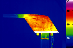
Ice formation
The thermography of a Boeing 737-800 Pitot probe with heating activated is shown below. This example, provided in 2012 by the Irish Air Accident Investigation Unit (AAIU), shows that in a poorly designed system heat (red) might not reach the tip of the tube, where ice can form and corrupt airspeed measurements.
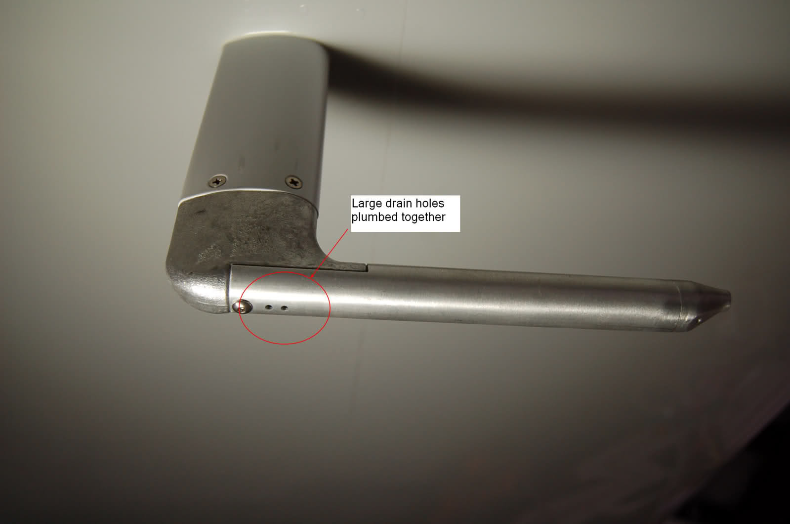
Most Pitot tubes have one or more drain holes connected to the pressure chamber. The tube are made essentially “self-draining” by the presence of the holes. They are used to drain away atmospheric water and other contaminants preserving the proper functioning of cockpit indicators connected to the Pitot-static system.
If the pitot tube becomes blocked, and its drain hole remains clear, the airspeed will read zero.
If the Pitot tube and its drain hole are blocked, the airspeed indicator will act like an altimeter, reading higher airspeeds with an increase in altitude. This situation can be dangerous if not recognized immediately.
If the static ports become blocked and the Pitot tube remains operable, the airspeed indicator will barely work and indications will be inaccurate.
Pitot heat is turned on by the pilot anytime ice is suspected in order to melt any amount of ice which might grow in size over the tube and create an erroneous reading or no reading at all on the airspeed indicator.
On the several airplanes the Pitot heat is automatically turned on once aircraft power is established (low heat) and then switches mode in the air (high heat). The heating system can be made fully automatic and the crew only learns about failures through EICAS (Engine Indicating and Crew Alerting System) o ECAM (Electronic Centralised Aircraft Monitor) and a dedicated light.
Digital display
High performance and jet transport category aircraft Pitot-static systems may be more complicated. They utilize digital air data computers (DADC). Essentially, all pressures and temperatures captured by sensors are fed into the ADC. Analog units utilize transducers to convert these to electrical values and manipulate them in various modules containing circuits designed to make the proper compensations for use by different instruments and systems.
A DADC usually receives its data in digital format. Systems that do not have digital sensor outputs will convert inputs into digital signals via an analog-to-digital converter.
Aircraft with three redundant systems and flight computer have the computer compare the readings and display appropriate message (airspeed disagree, altitude disagree, vertical speed disagree) and sound master warning if it detects mismatch larger than normal measurement error.
Managing inconsistent sensor readings
Even if the DADC does detect a fault by comparing the values from the separate systems, it does not know which of the systems is wrong. The pilots must decide themselves by combining other information they have and their understanding of physics of flight.
In smaller aircraft that do not have redundant Pitot-static systems and in older aircraft without flight computer it is up to the pilot(s) to spot the problem.
With one or more unreliable airspeed indications – which is one of the most critical situations – the initial action is not to start troubleshooting/figuring out which indicator is ‘the correct one’, but to ensure safe speed/flight path by other means.
For instance, the initial actions on Boeing aircraft is to disconnect automatics (autothrottle, autopilot, flight director) and control the aircraft given memorized combinations of pitch and thrust (or read from pitch-thrust tables). With the aircraft under control, and when directed by the checklist, pilots start analyzing the situation, to see if they can rectify/isolate the faulty source. If a reliable source can not be determined, the aircraft continues to be flown by pitch/thrust settings given in the manual (based on altitude, if known, weight, flaps/gear, desired vertical profile).
Erroneous airspeed/altitude indications often imply each other, as an unreliable static pressure source will affect both.