The Anatomy of Conventional Aircraft Configurations
This section introduces a set of definitions pertaining the architecture of conventional fixed-wing airplanes, which are useful in the discussion of aircraft performance characteristics as well as of aircraft stability and control. Since pilots already possess a knowledge of aircraft fundamentals by training, the various concepts are introduced here in view of an effective presentation of the flight theory as an engineering discipline. The knowledge of basic facts in aerodynamics is assumed.
Aircraft Body Axes
The figure below represents an airplane with a conventional three-axis architecture aircraft. A reference frame \(\{ G, x, y, z \}\) fixed with the vehicle is also shown.
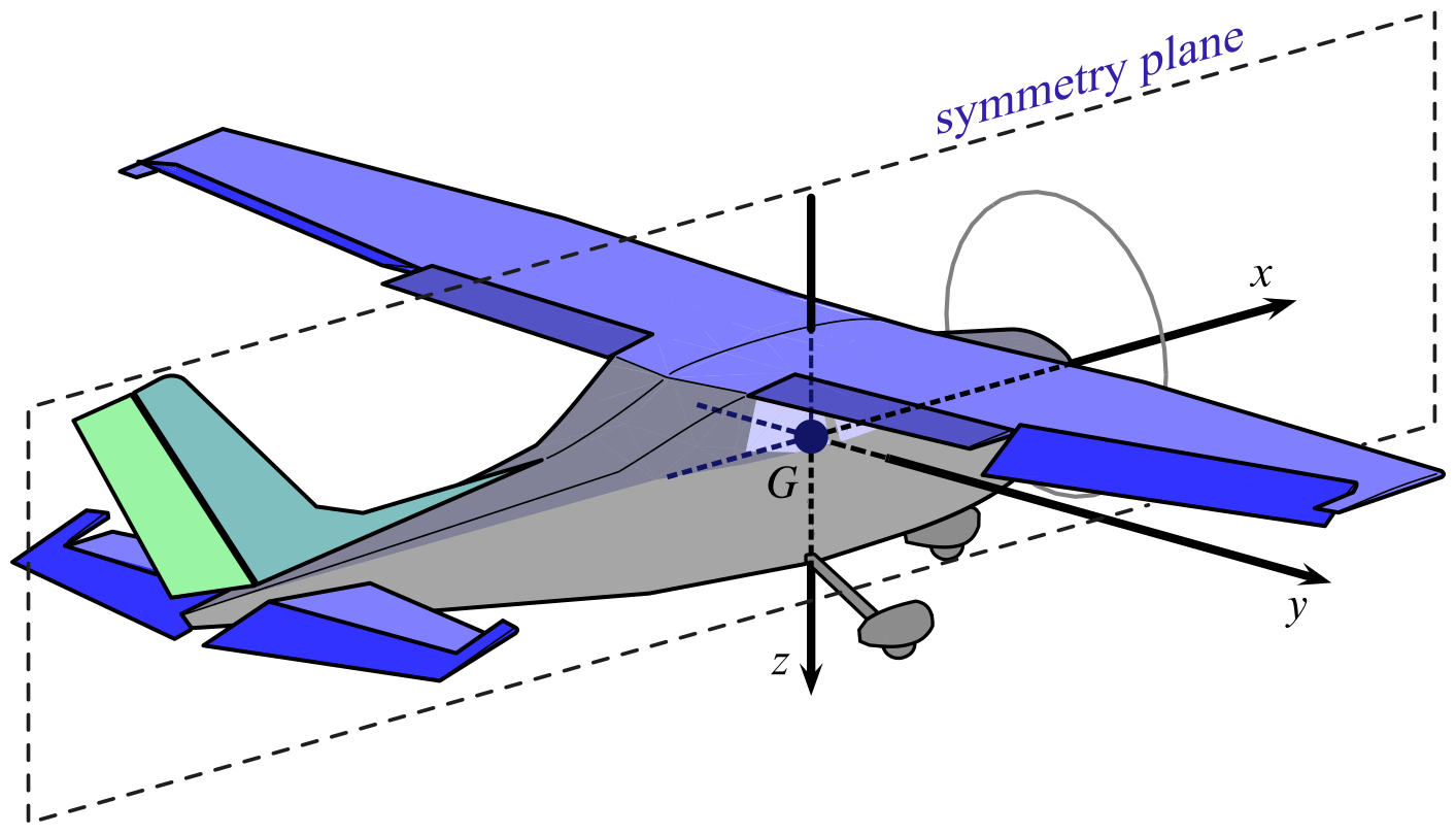
This cartesian reference is called aircraft body-frame. The origin $G$ coincides with the aircraft center of gravity (CoG) and the three axes are oriented as shown. For this reason the body-axes are also named $x_\mathrm{B}$, $y_\mathrm{B}$, and $z_\mathrm{B}$. The first axis $x_\mathrm{B}$ is directed along the fuselage longitudinal dimension and points forwards. The second body axis $y_\mathrm{B}$ is normal to the fuselage symmetry plane and is positively oriented towards the right wing tip. The third axis $z_\mathrm{B}$ completes the cartesian frame and points towards the fuselage belly.

Planform definitions
The figure below shows a top view af an aircraft.
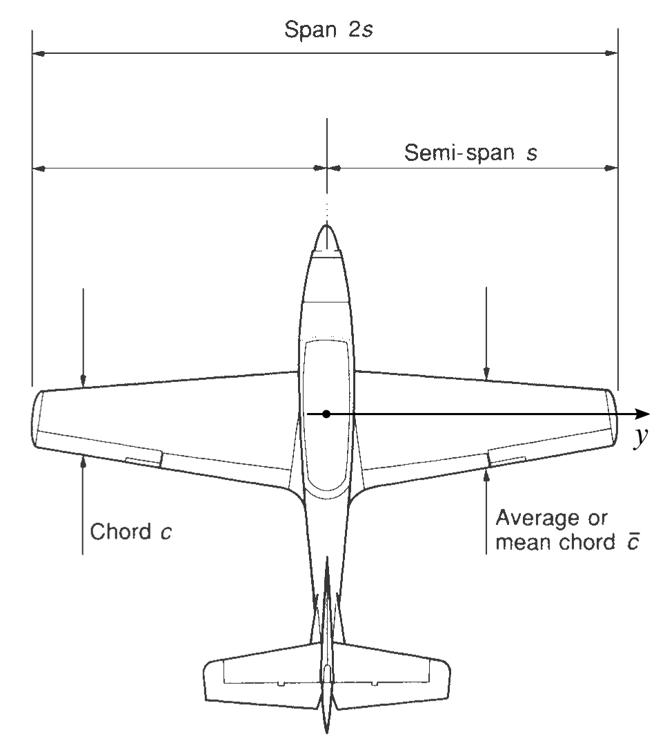
Two of the quantities that characterize the wing planform are also shown:
- $b=2s$, the wing span;
- $\bar{c}$, the mean chord, taken over all the chords $c(y)$ at wing sections $y$ for $-\frac{b}{2} \le y \le +\frac{b}{2}$.
The sections of a wing with planes parallel to the fuselage symmetry plane $x_\mathrm{B}z_\mathrm{B}$ have the shapes of airfoils. Wings owe to them their capacity to develop a lift force able to support the weight of the aircraft in flight, with a relatively small resistance.
Wing-Fuselage definitions
A more detailed nomenclature is given by the next drawing, representing a top and a side view of a wing-fuselage combination.
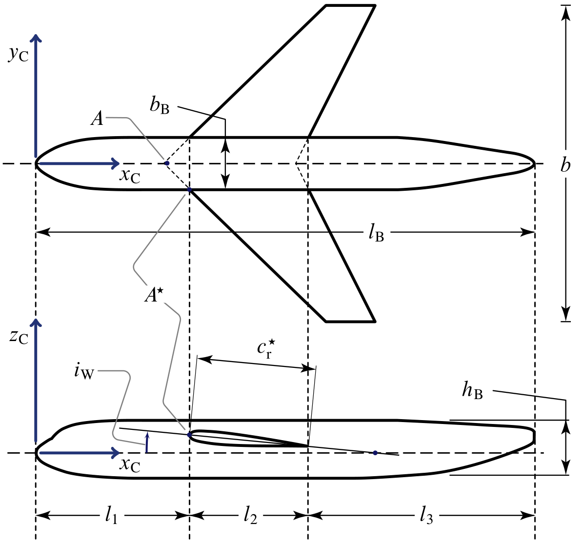
The axes $x_\mathrm{C}$, $y_\mathrm{C}$, and $z_\mathrm{C}$ are what designers call construction axes. Like the body-axes, also the construction axes are fixed with the aircraft but are oriented differently. In the above illustration the various quantities are used to identify the position of the wing relative to the fuselage body. Typically, the body and construction axes $x_\mathrm{B}$ and $x_\mathrm{C}$ are parallel, but the latter is non-baricentric, originates at the fuselage nose and points backwards. A longitudinal axis ($x_\mathrm{B}$ or $x_\mathrm{C}$) is also called fuselage reference line (FRL).
The quantities represented above have the following significance:
- $l_\mathrm{B}$, fuselage length;
- $b_\mathrm{B}$, $h_\mathrm{B}$, maximum fuselage width and fuselage height;
- $A$, wing apex point, i.e. leading edge of the wing root when wing leading edge line is ideally extended up to the symmetry plane;
- $A^\star$, leading edge of the effective wing root, i.e. of the attachment profile at the wing-fuselage junction;
- $c_{\mathrm{r}}^\star$, chord of the effective wing root;
- $i_{\mathrm{W}}$, wing incidence or wing rigging angle, i.e. a mounting angle formed by the wing root chord and the fuselage reference line $x_\mathrm{C}$.
The next figure shows a front view the wing-fuselage combination.
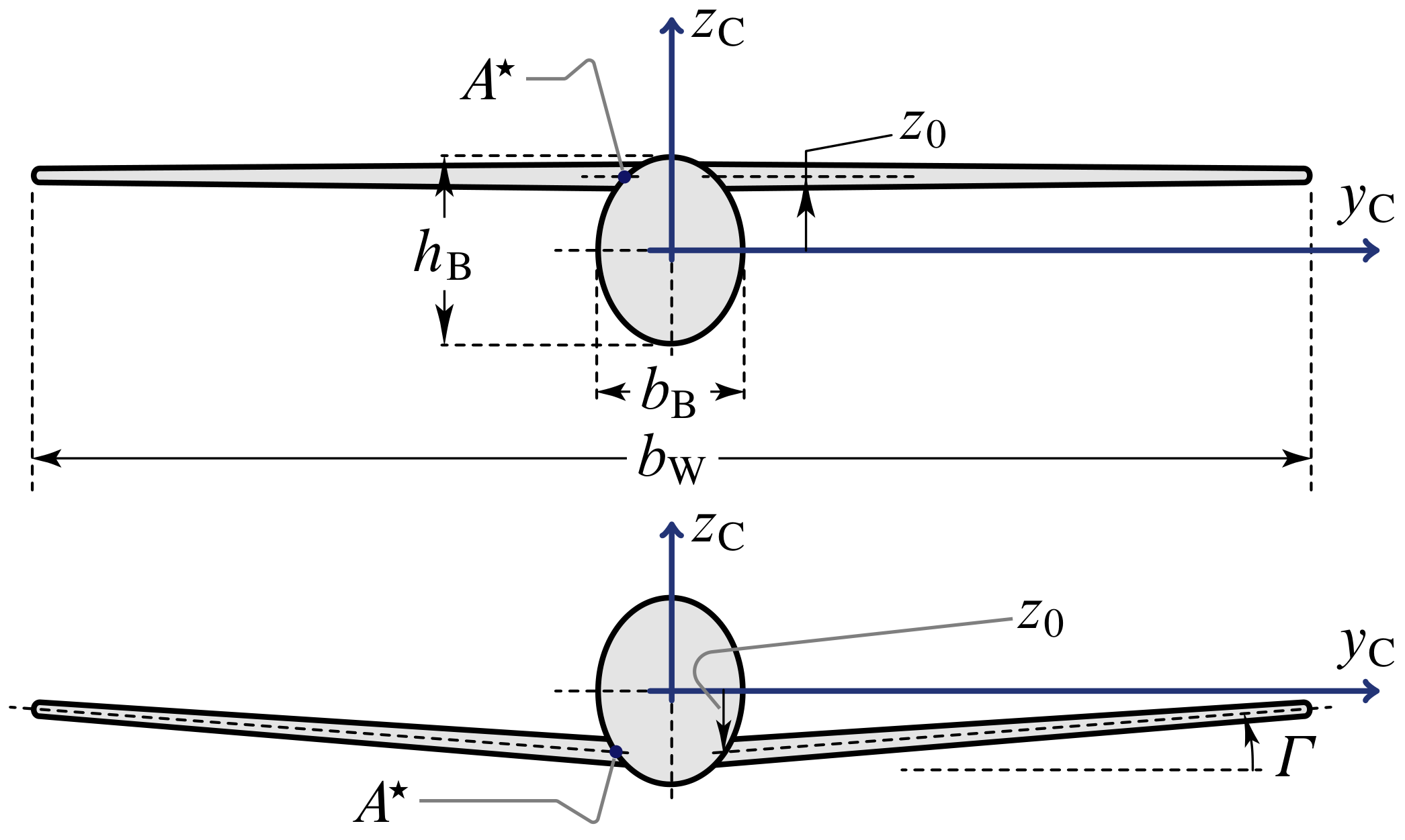
Two more quantities are introduced:
- $\Gamma$, the wing dihedral angle, positive as shown;
- $z_0$, the vertical position of the wing with respect to the fuselage transverse reference line $y_\mathrm{C}$.
The Wing Zero-Lift Direction in Aircraft Configurations
An important angle, related to the lift capacity of the wing of a given aircraft, is that formed by the relative wind velocity vector \(\boldsymbol{V}_{\!\infty}\) with the wing zero-lift direction. This direction is defined below.
Wing Twist and Local Airfoil Zero-Lift Angles
The next figure shows a side view of a wing where the root and tip airfoils are emphasized. All wing sections, at each possible spanwise station $-\frac{b}{2} \le y \le +\frac{b}{2}$, have a chord $c(y)$ which is geometrically twisted with respect to the root chord direction. The local geometric twist angle is called $\varepsilon_{\mathrm{g}}(y)$. The geometric twist is negative by definition if the local chord is pitched down with respect to the root chord — this is called wash out angle by designers.
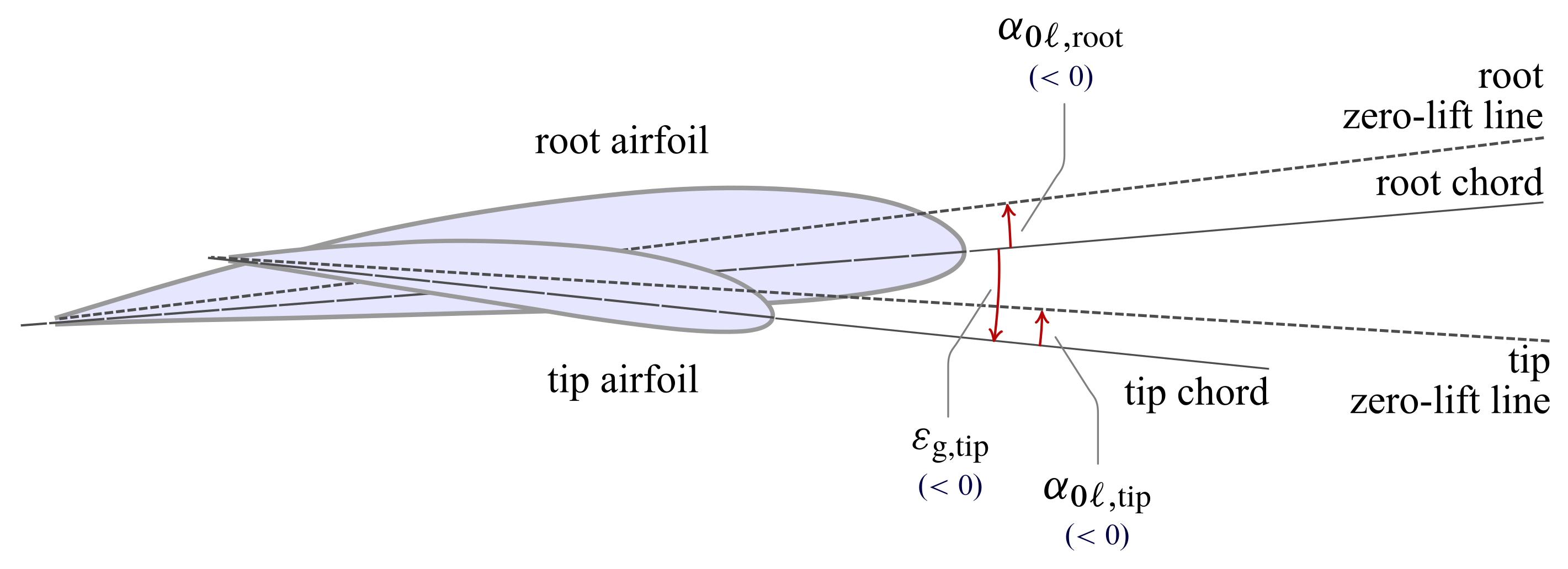
The quantities represented above have the following significance:
- $\varepsilon_{\mathrm{g,tip}}$, geometric wing twist,
- $\alpha_{0\ell,\mathrm{root}}$, zero-lift angle of the wing root airfoil;
- $\alpha_{0\ell,\mathrm{tip}}$, zero-lift angle of the wing tip airfoil.
The generic airfoil at the station $y$ is an characterized by a local zero-lift direction inclined of an angle $\alpha_{0\ell}(y)$ with respect to the local chord. Typically, this angle is negative value for positively cambered profiles and is reported in the following qualitative plot:
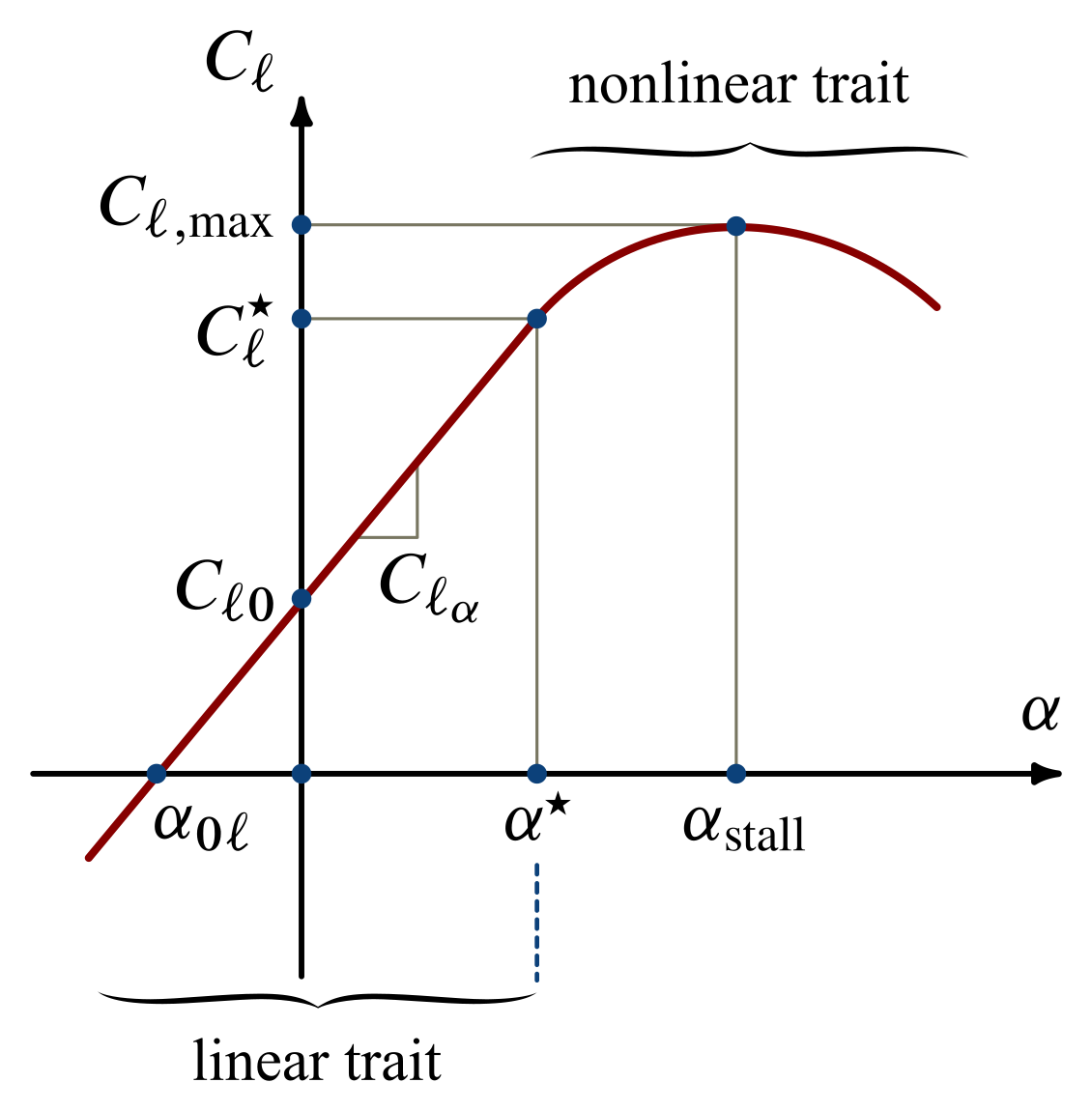
The above curve gives the nondimensional lift per unit span $\ell (y)$, which is known to vary linearly with the local angle of attack $\alpha(y)$, being zero when the relative wind meets the profile according to the local zero-lift direction.
Wing angle of attack
By definition, the angle of attack of a three-dimensional wing is the angle $\alpha_\mathrm{W}$ formed by the relative wind direction with the root chord line. A positive wing angle of attack is represented in the next figure.
Wing zero-lift angle of attack
It is important to recognize that the relative wind might invest the finite wing in such a way that the total lift $L$ developed by the surface is zero. This defines the wing zero-lift direction forming an angle $\alpha_{0L,\mathrm{W}}$ with the root chord, i.e. the wing zero-lift angle.
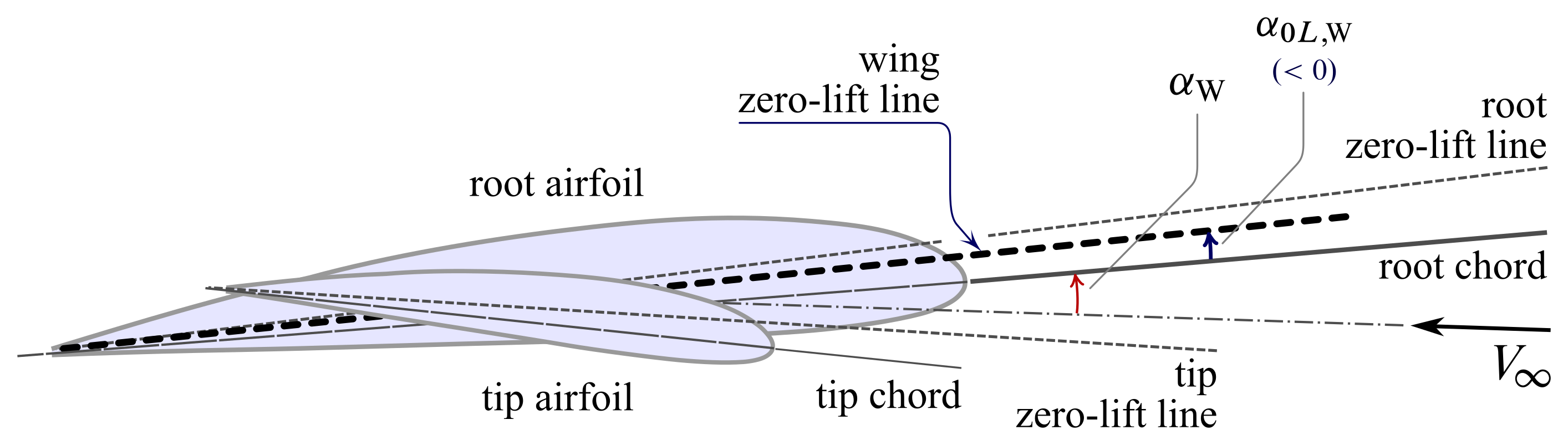
The above picture shows a typical arrangement of wing airfoils, with the resulting wing zero-lift line pitched slightly upwards with respect to the root chord. This corresponds to a negative $\alpha_{0L,\mathrm{W}}$.
Wing absolute angle of attack
Aerodynamicists elegantly explain that the lift of a wing is due to the absolute angle of attack
\begin{equation} \alpha_{\mathrm{a,W}} = \alpha_{\mathrm{W}} - \alpha_{0L,\mathrm{W}} \label{eq:Wing:Absolute:AoA} \end{equation}
i.e. the angle between the relative wind and the zero-lift line. A zero absolute angle of attack means a zero wing lift. An $\alpha_{\mathrm{a,W}} < 0$ results in a downward oriented, hence negative, lift. A positive $\alpha_{\mathrm{a,W}}$ corresponds to a positive $L$.
The above concepts are found in the next qualitative plot. The wing lift coefficient $C_L$ versus $\alpha_\mathrm{W}$ exhibits a typical linear trait intersecting the horizontal axis at the negative abscissa $\alpha_{0L,\mathrm{W}}$.
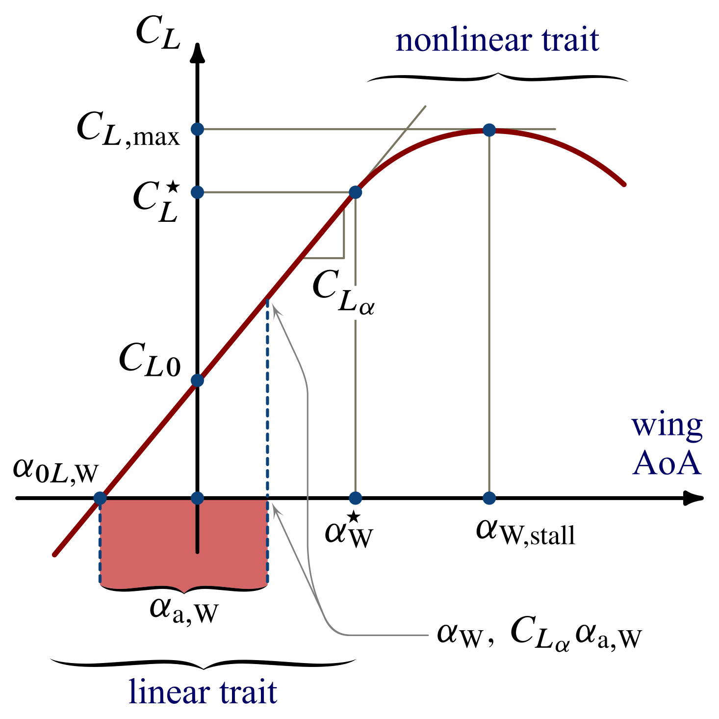
For a given $\alpha_{\mathrm{W}}$ in the linear range (i.e. less than the value $\alpha_{\mathrm{W}}^\star$), the wing lift coefficient is simply given by the lift curve slope $C_{L_\alpha}$ times the absolute angle of attack:
\begin{equation} C_L = C_{L_\alpha} \, \alpha_{\mathrm{a,W}} \label{eq:Wing:Absolute:AoA:CL} \end{equation}
which is a concise way of espressing the linear dependence
\begin{equation} C_L = C_{L0} + C_{L_\alpha} \, \alpha_{\mathrm{W}} \label{eq:Wing:AoA:CL:Linear} \end{equation}
where $C_{L0} = C_{L_\alpha} \big|\alpha_{0L,\mathrm{W}}\big|$.
Aircraft angle of attack
As a matter of fact, the above definitions have to be refined further considering that a wing of a conventional aircraft is not isolated but is mounted onto the fuselage. From the perspective of flight the angle of attack of the aircraft is the angle $\alpha_\mathrm{B}$ formed by the relative wind with the reference axis $x_\mathrm{B}$ of the fuselage. This angle is reported in the figure below.
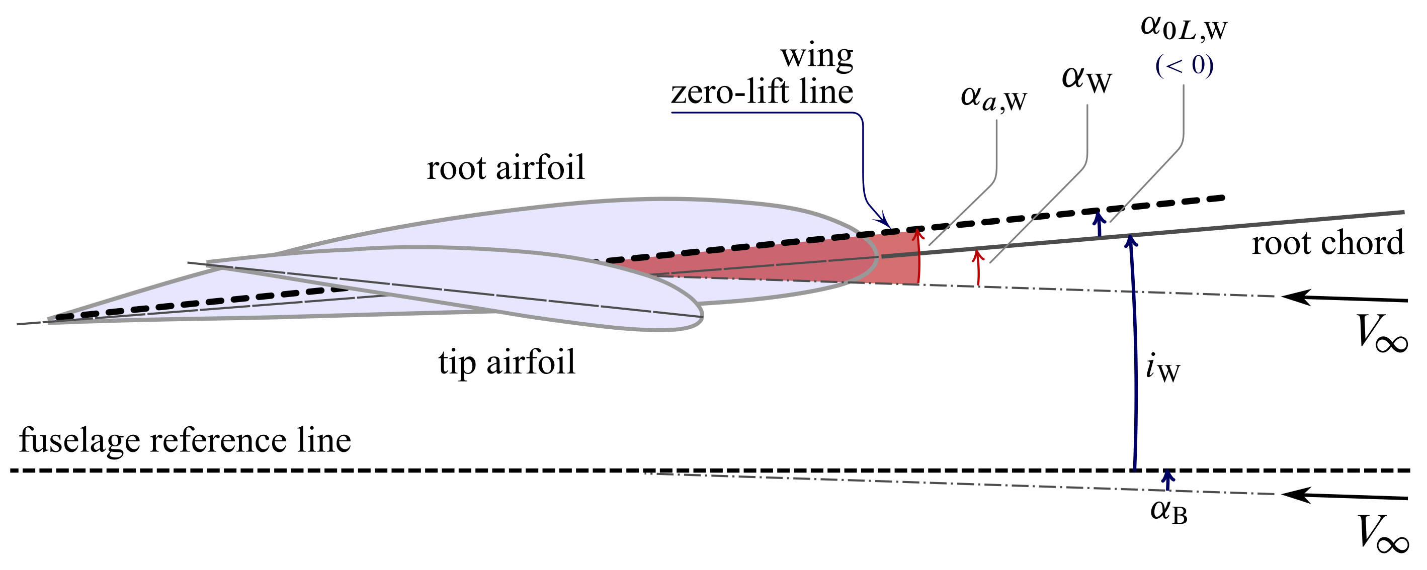
The sum of $\alpha_{\mathrm{B}}$ and of the rigging angle $i_\mathrm{W}$ is obviously equal to the wing angle of attack:
\begin{equation} \alpha_\mathrm{B} + i_\mathrm{W} = \alpha_{\mathrm{W}} \label{eq:Body:Wing:AoA} \end{equation}
hence:
\begin{equation} \alpha_{\mathrm{a,W}} = \alpha_\mathrm{B} + i_\mathrm{W} - \alpha_{0L,\mathrm{W}} \label{eq:Body:Wing:Absolute:AoA} \end{equation}
Wing Zero-Lift Line Representation in Aircraft Body-Axes
Consider a wings level flight, occurring along a horizontal trajectory of the CoG with no atmospheric wind. In this circumstance the vector \(\boldsymbol{V}_{\!\infty}\) is horizontal and opposite to the flight velocity $\boldsymbol{V}$. A nonzero angle $\alpha_\mathrm{B}$ corresponds to a fuselage travelling with a pitched attitude with respect to the horizontal, as represented in the next figure. The effective angle formed by \(\boldsymbol{V}_{\!\infty}\) and the wing zero-lift line is $\alpha_\mathrm{B} + i_\mathrm{w} - \alpha_{0L,\mathrm{W}}$, i.e. the aircraft absolute angle of attack $\alpha_\mathrm{a,B}$.
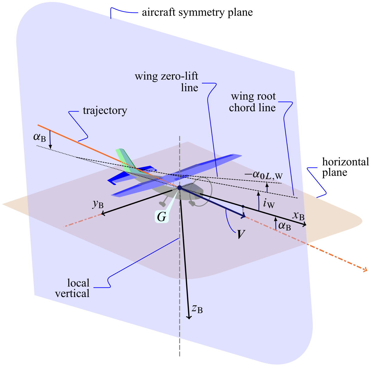
In the particular case of a flight with horizontal fuselage, i.e. $\alpha_\mathrm{B} = 0$, the aircraft absolute angle of attack becomes:
\begin{equation} \mu_x = i_\mathrm{w} - \alpha_{0L,\mathrm{W}} \label{eq:AC:mux} \end{equation}
This angle is shown in the next figure.
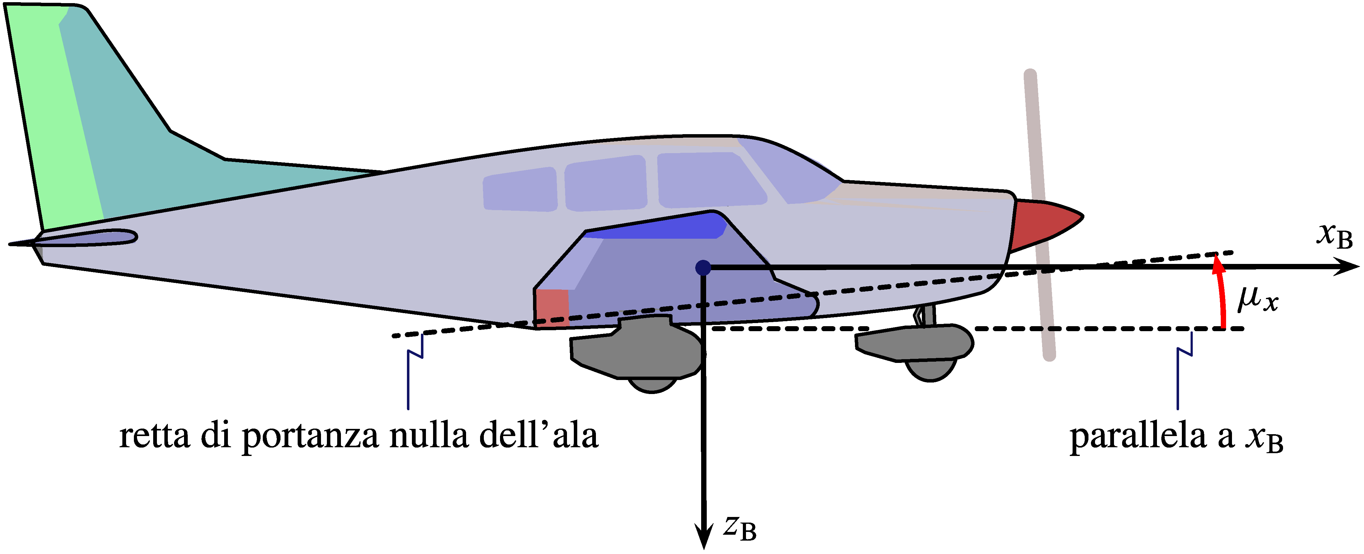
In a wings level flight, along a horizontal trajectory, with a zero pitching attitude of the fuselage, the angle $\mu_x$ is responsible for the lift supporting the aircraft (assuming, approximately, that the whole lift is given by the wing).
Fuselage definitions
Some geometric parameters of a fuselage are represented in the next drawing.
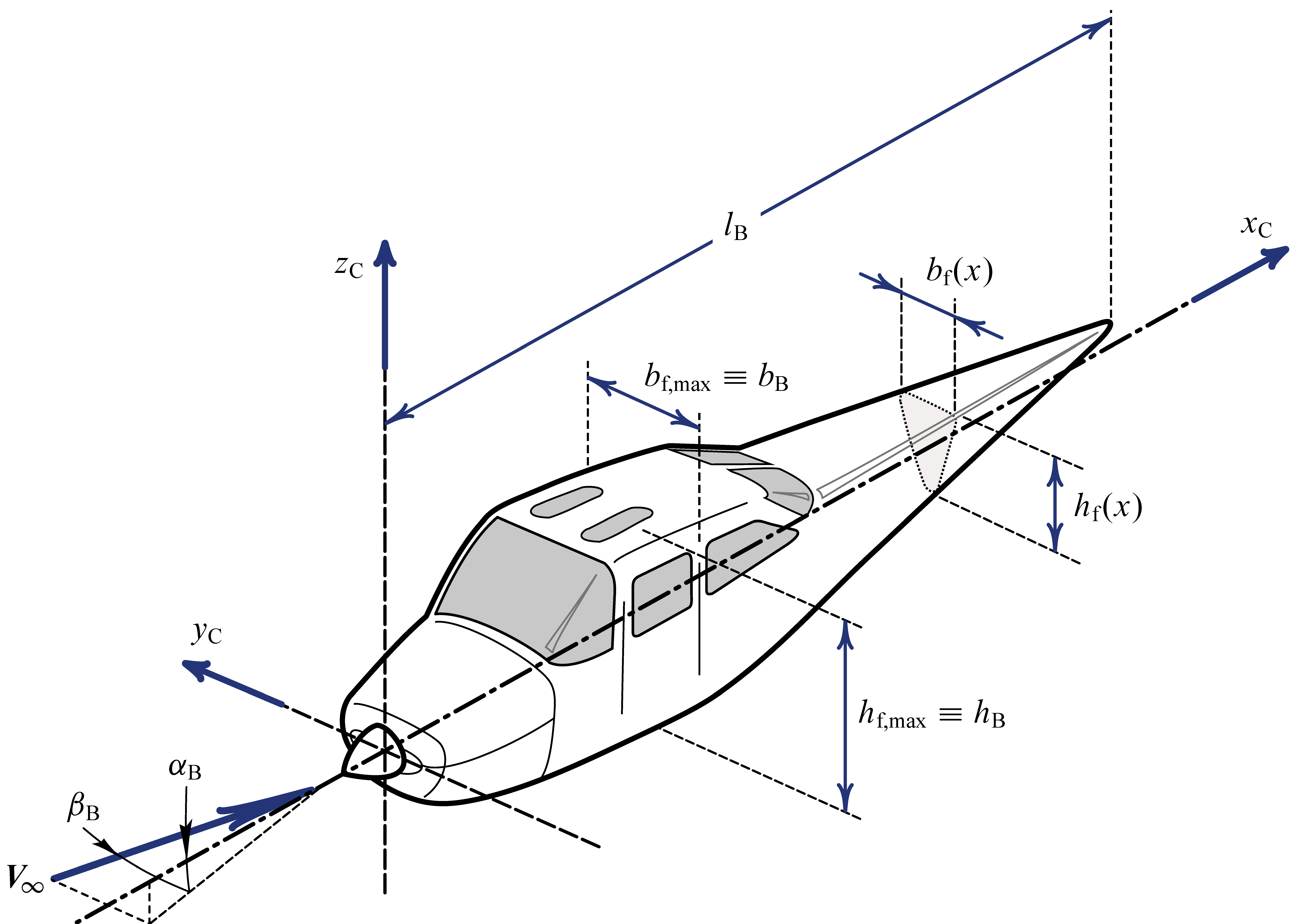
This figure shows the common definition of the two aerodynamic angles that define the orientation of the relative wind velocity vector with respect to the fuselage, and hence to the entire aircraft. These angles are $\alpha_\mathrm{B}$ — already discussed above — and the sideslip angle $\beta_\mathrm{B}$ (or simply $\beta$).
It might occur in flight that the relative wind is out of the aircraft symmetry plane. When the the pilot sees a current coming from the right it means that the aircraft is sideslipping with a positive angle $\beta$. This is the angle formed by the velocity vector \(\boldsymbol{V}_{\!\infty}\) and the plane $x_\mathrm{C} z_\mathrm{C} = x_\mathrm{B} z_\mathrm{B}$. The projection of \(\boldsymbol{V}_{\!\infty}\) into the plane is then used to measure the aircraft angle of attack $\alpha_\mathrm{B}$.
The Horizontal Tailplane
The geometric parameters defining the position of the horizontal tailplane with respect to the fuselage are shown in the next two figures.
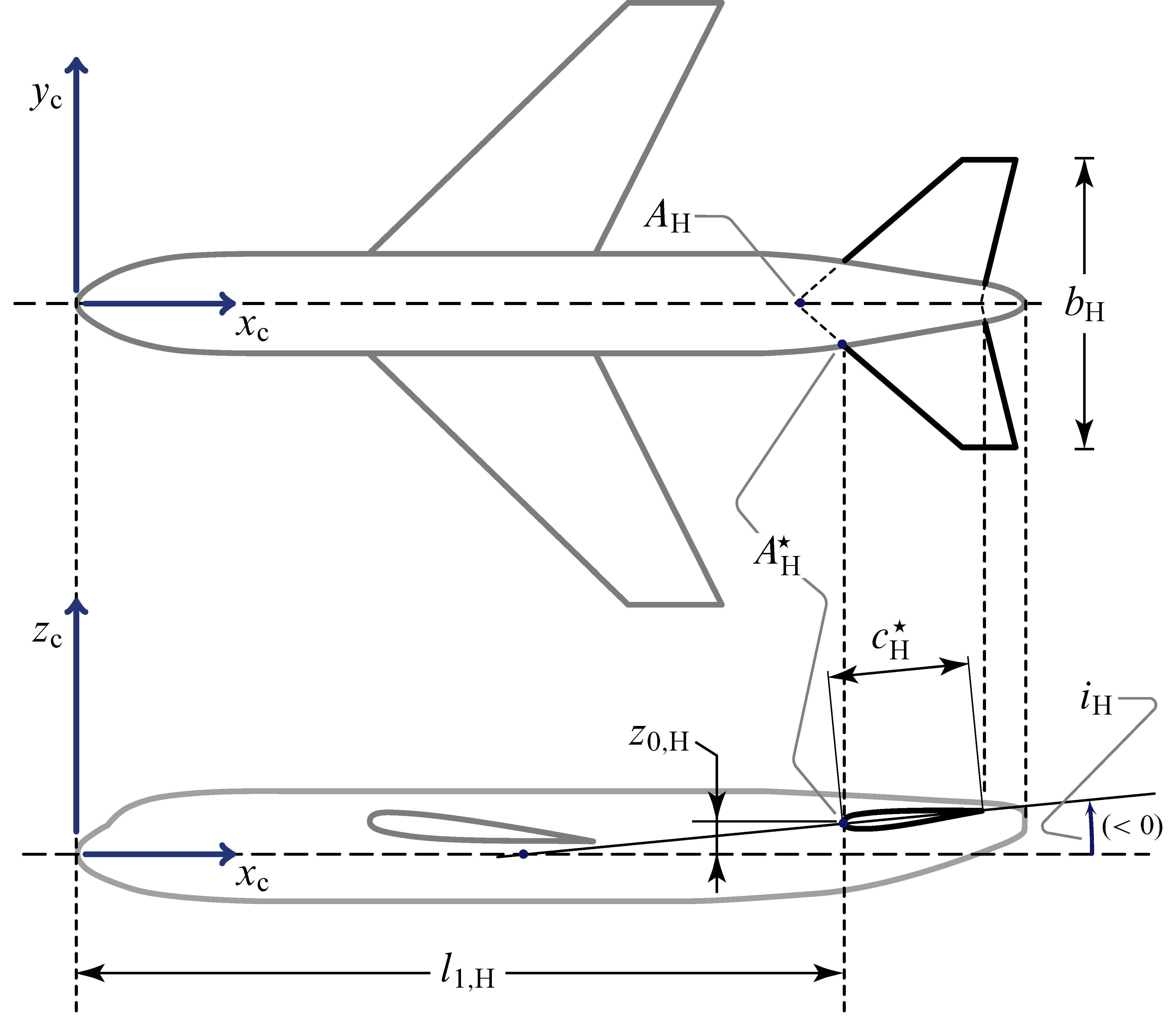
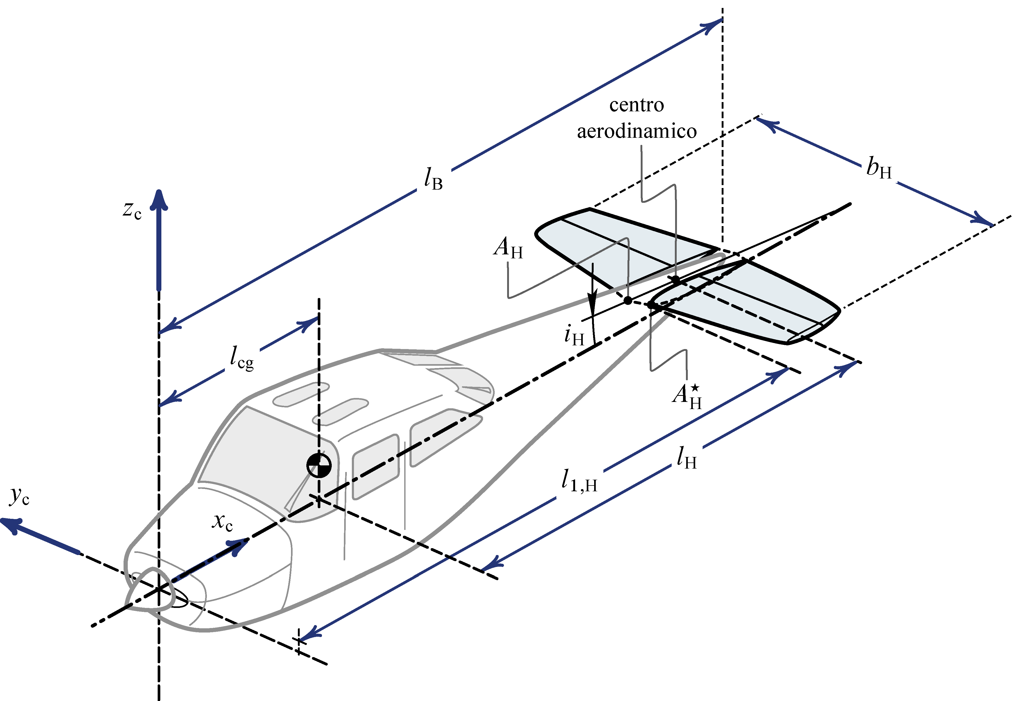
All parameters in the above drawings are defined similarly to their wing’s counterparts. In case of a horizontal tail a subscript $( \cdot )_ {\mathrm{H}}$ is used. The distance $l_\mathrm{H}$ is an important feature of conventional aircraft configurations, that is the arm between the tail aerodynamic center and the aircraft CoG.
The tailplane is anything other than a small wing placed in a rear position with respect to the main lifting surface. This is a traditional arrangement that ensures a longitudinal stability to the aerodynamic configuration.
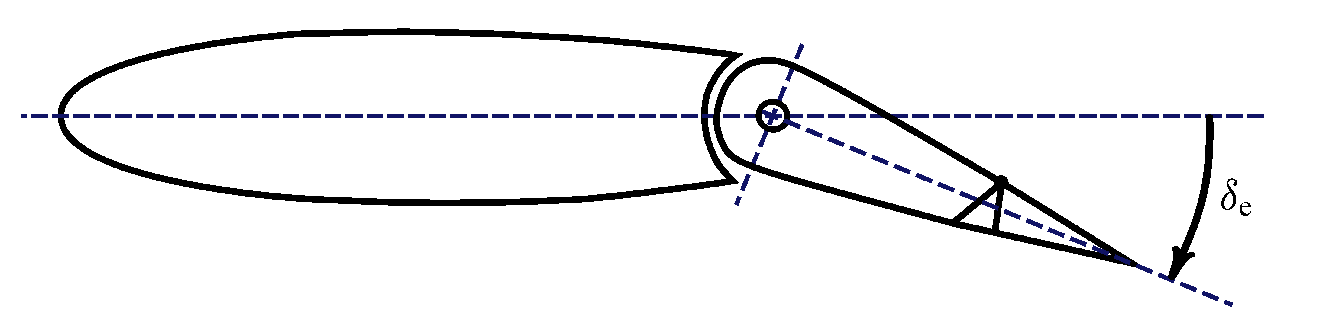
The next three figures give the details of a traditional tailplane with elevators. These movable surfaces, placed symmetrically on both half-tails, rotate of the same angle $\delta_\mathrm{e}$ and provide piching control to the pilot.
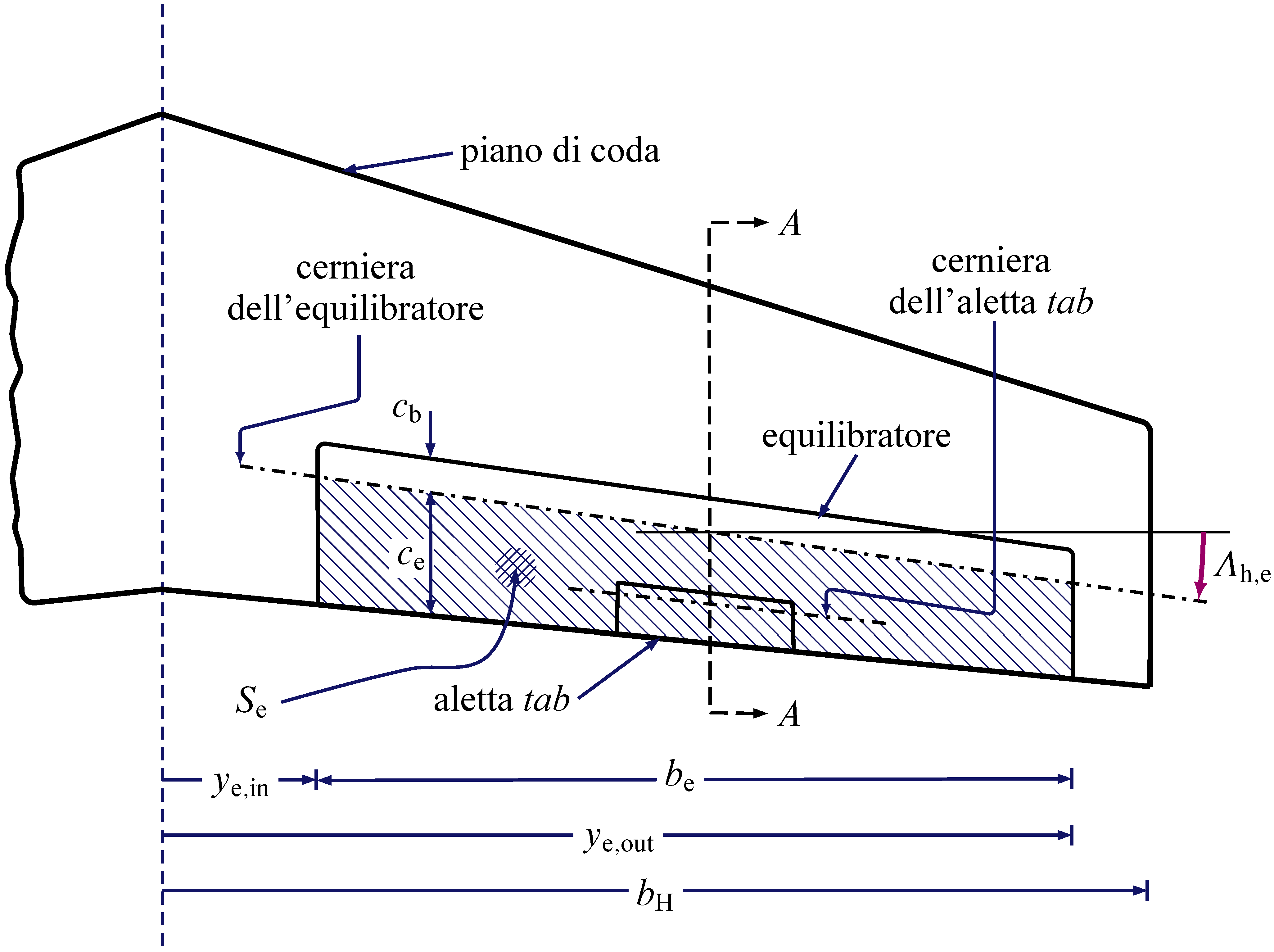
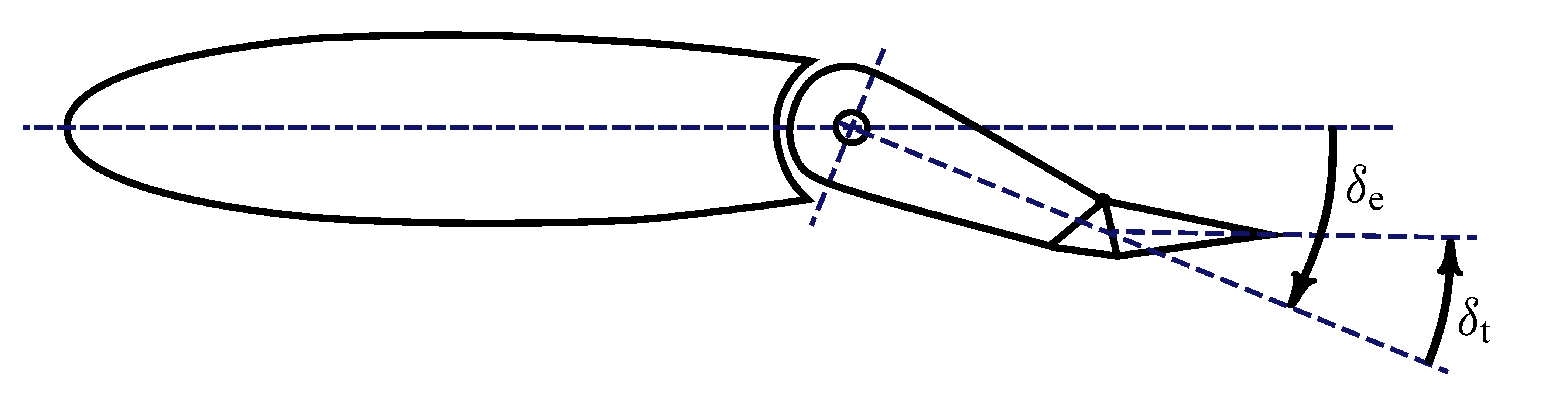
The elevator deflection angle $\delta_\mathrm{e}$ is shown in the next tailplane section drawings.
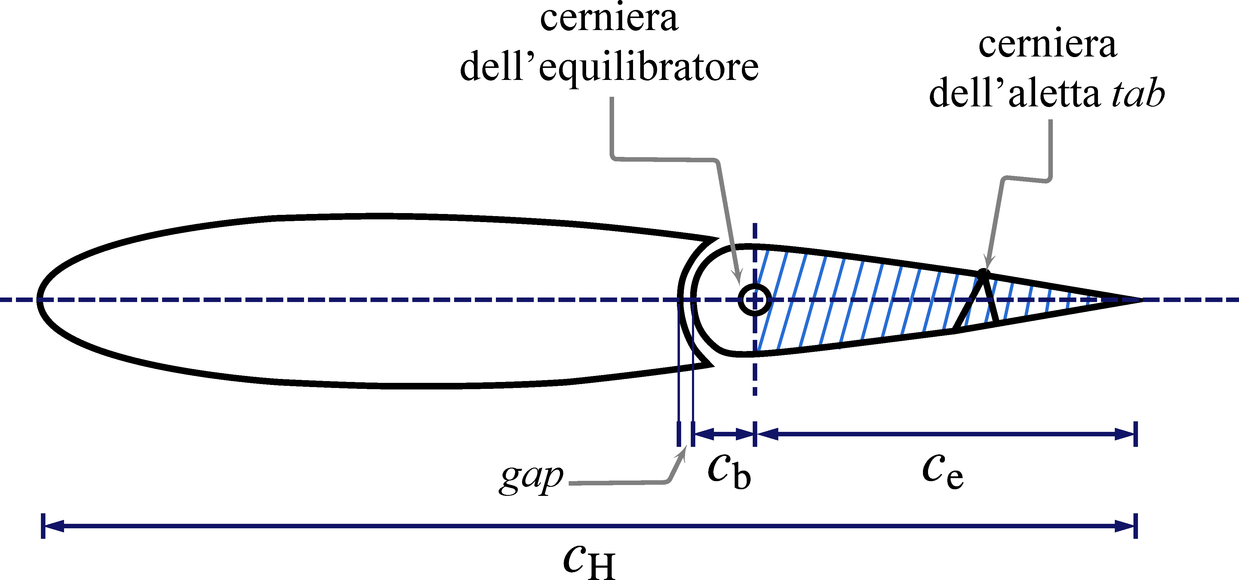
Typically, elevators have smaller movable tabs, called trim tabs, whose rotation $\delta_\mathrm{t}$ provides additional finer control of longitudinal equilibrium flight and of piloting loads.
The Vertical Tailplane
A nomenclature of the geometric parameters related to the vertical tailplane is reported in the next figure.
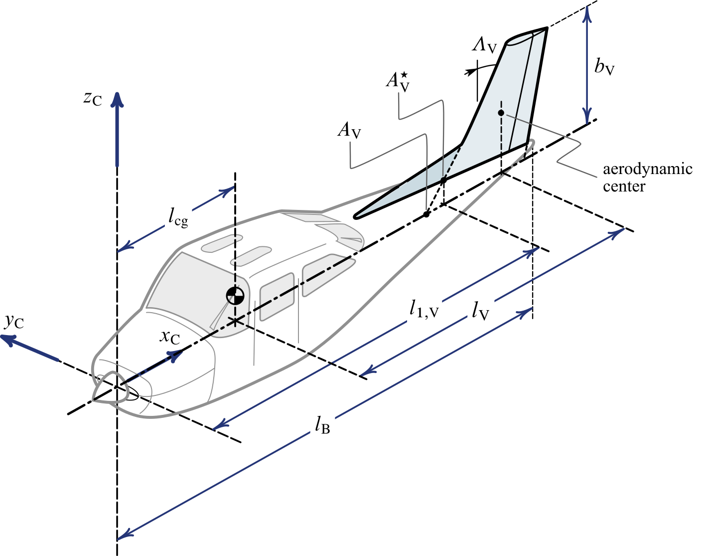
In case of a vertical tail a subscript $( \cdot )_ {\mathrm{V}}$ is used for all parameters similar to those related to the wing and to the horizontal tail. The distance $l_\mathrm{V}$ is an important feature of conventional aircraft configurations, that is the arm between the vertical tail aerodynamic center and the aircraft CoG.
The vertical tailplane is anything other than a small half-wing placed in a rear position with respect to the main lifting surface. This is a traditional arrangement that ensures a directional stability to the aerodynamic configuration.
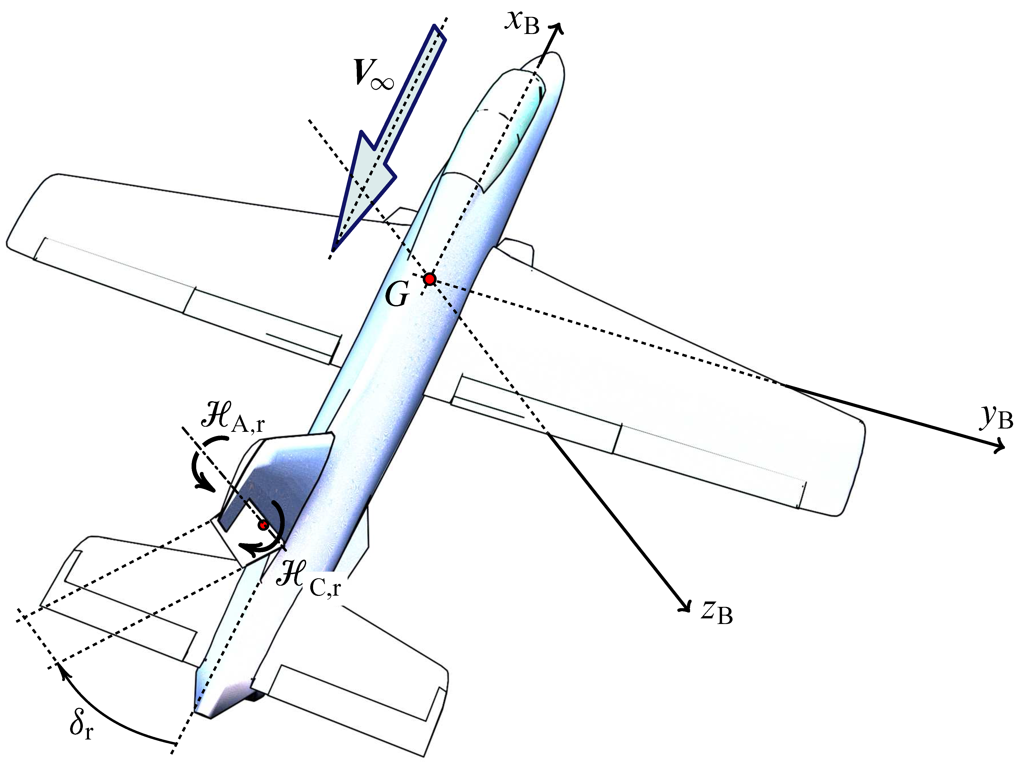
The figure below shows a typical rudder deflected to control the aircraft yawing motion. When the pilot acts on cockpit pedals the rudder rotates of the angle $\delta_\mathrm{r}$ around its hinge line. A positive deflection is shown in the picture.
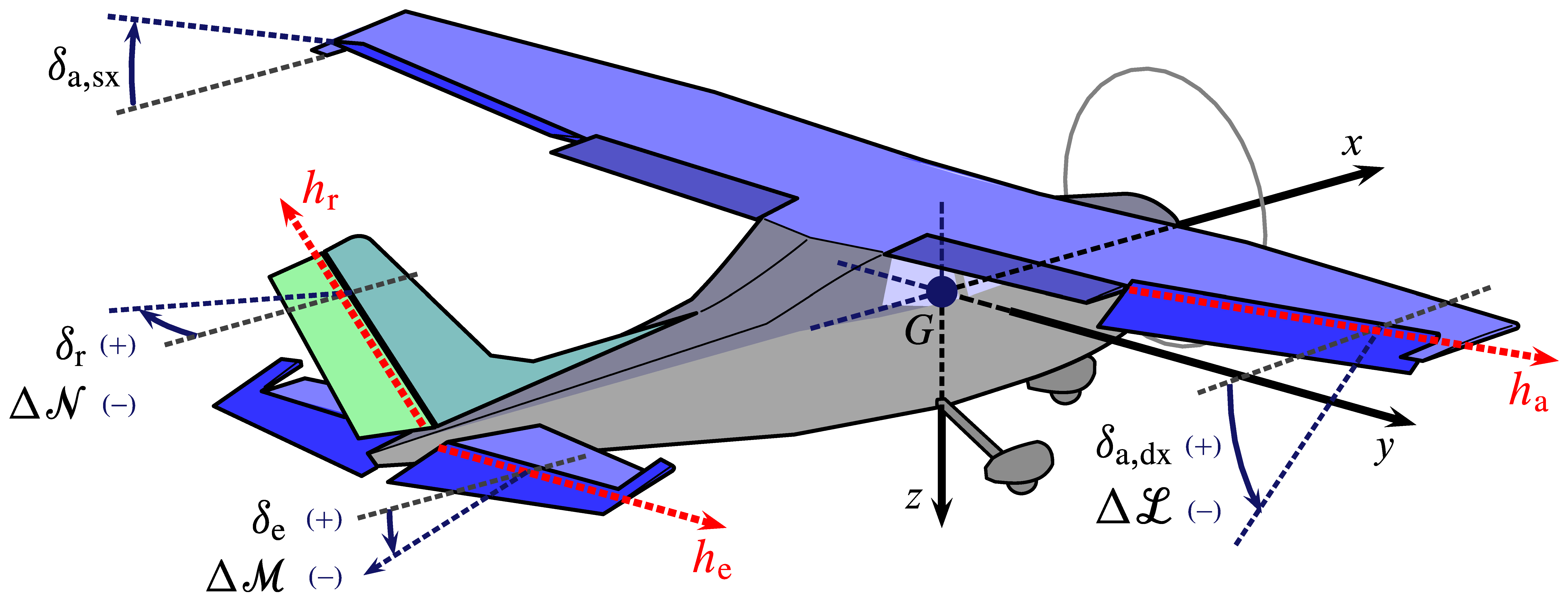
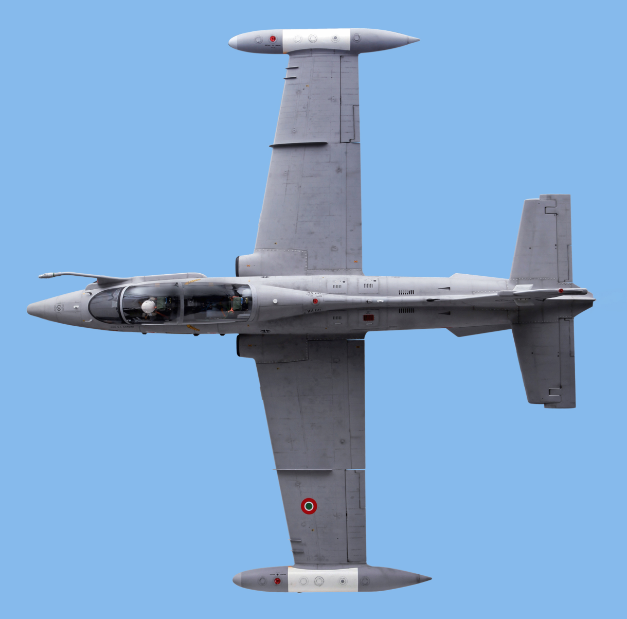
Conventional Flight Controls
The conventional flight controls of a military jet trainer (Aermacchi MB-339) are shown in the next two figures.
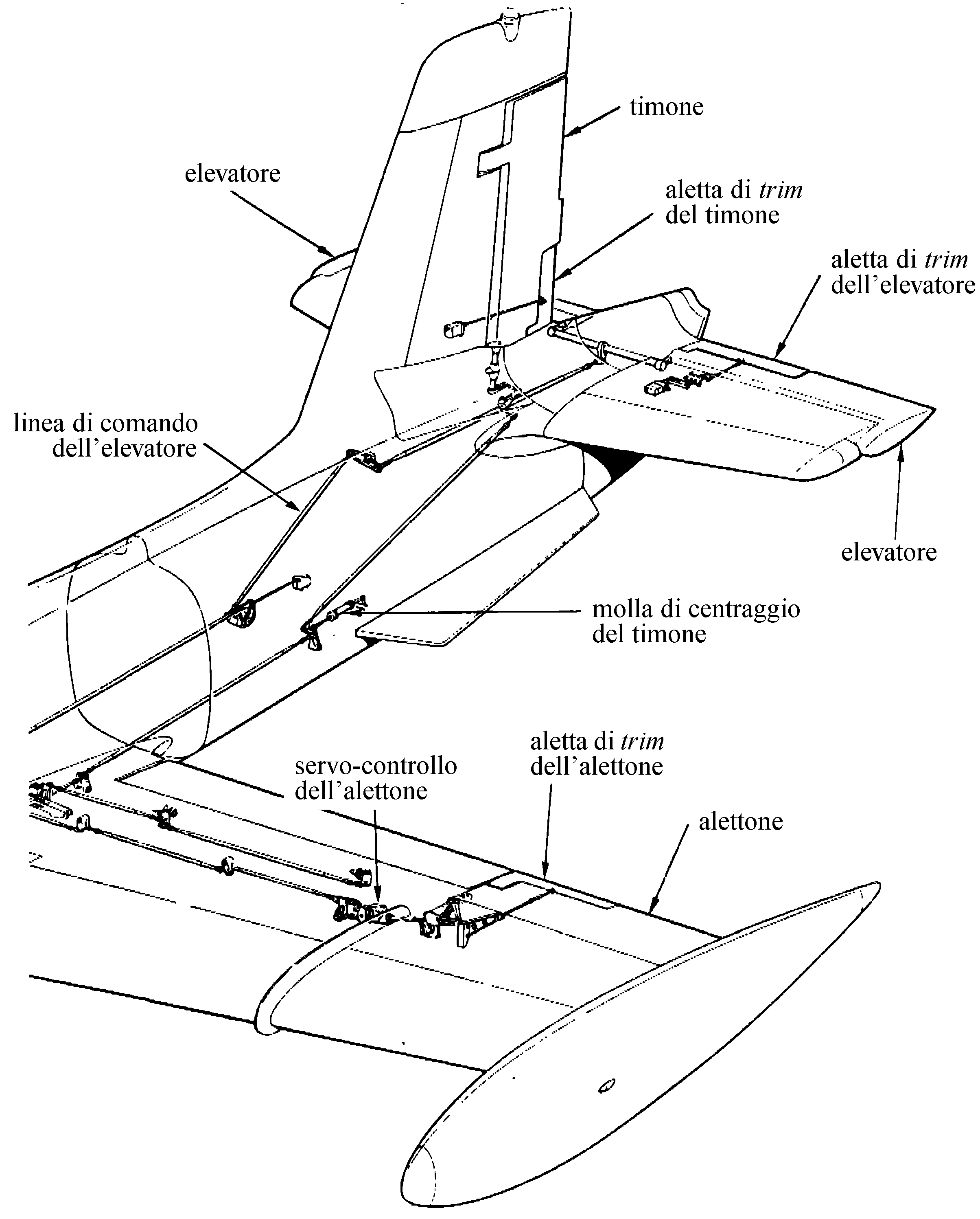
Aircraft with a conventional architectural configuration are often called ‘three-axis airplanes’ because the pilot is able to control the vehicle attitude change and the rotational equilibrium about the three body axes. These are called: roll axis $x_\mathrm{B}$, pitch axis $y_\mathrm{B}$, and yaw axis $z_\mathrm{B}$. The control actions are actuated by means of, respectively, the ailerons, the elevator, and the rudder.
Positive signs of aerosurface deflections (according to the European convention) are shown in the next figure.